by Łukasz Jakóbiec
the Printer v4
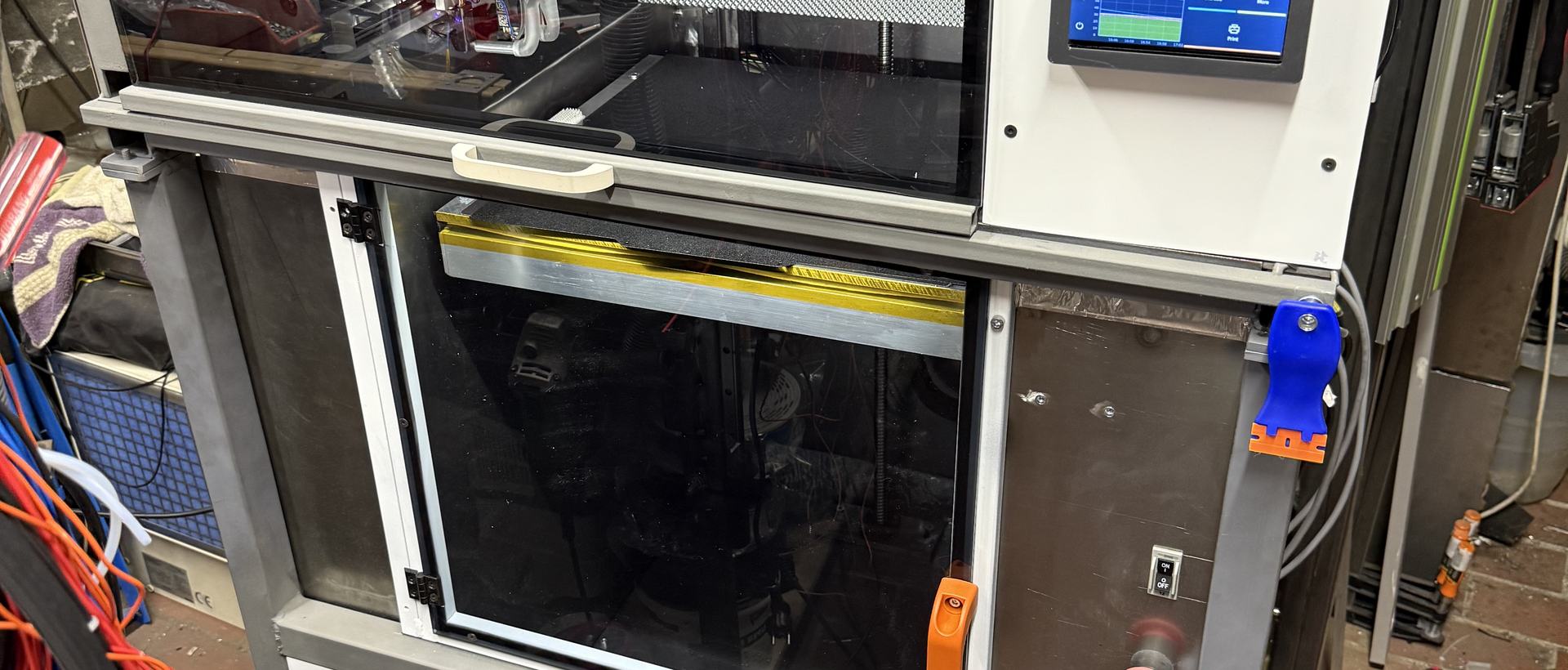
After DWG printer and then a printer that was using belts the time came to build a proper printer
My printers evolved with time, and one after another, the shortcomings became obvious. One was the always-open structure, which I tried to mitigate as an afterthought. One issue with an open structure is dust; it loves to settle on the print bed, and after a while it starts affecting bed adhesion. The second issue is the smell, or the particulates the printer releases as it extrudes heated, molten plastic. The third issue is temperature variation affecting the printer models.
It was time to disassemble the second printer version and salvage the AC servos, ball screw, linear rails, and... that's it. The rest got upgraded.
Where things landed (at least for now):
- 100W AC servos driving each axis
- Klipper as the firmware
- CAN bus for hotends
- IDEX (two extruders on the same Y axis)
- 800W 230V heatbed with magnetic PEI-coated sheets 450x430mm
- Fully enclosed with thermal insulation for the chamber
- Heated chamber (not done yet)
- Integrated storage drawer for filament with drying capability (not done yet)
- Capacity to use 3kg and 5kg spools
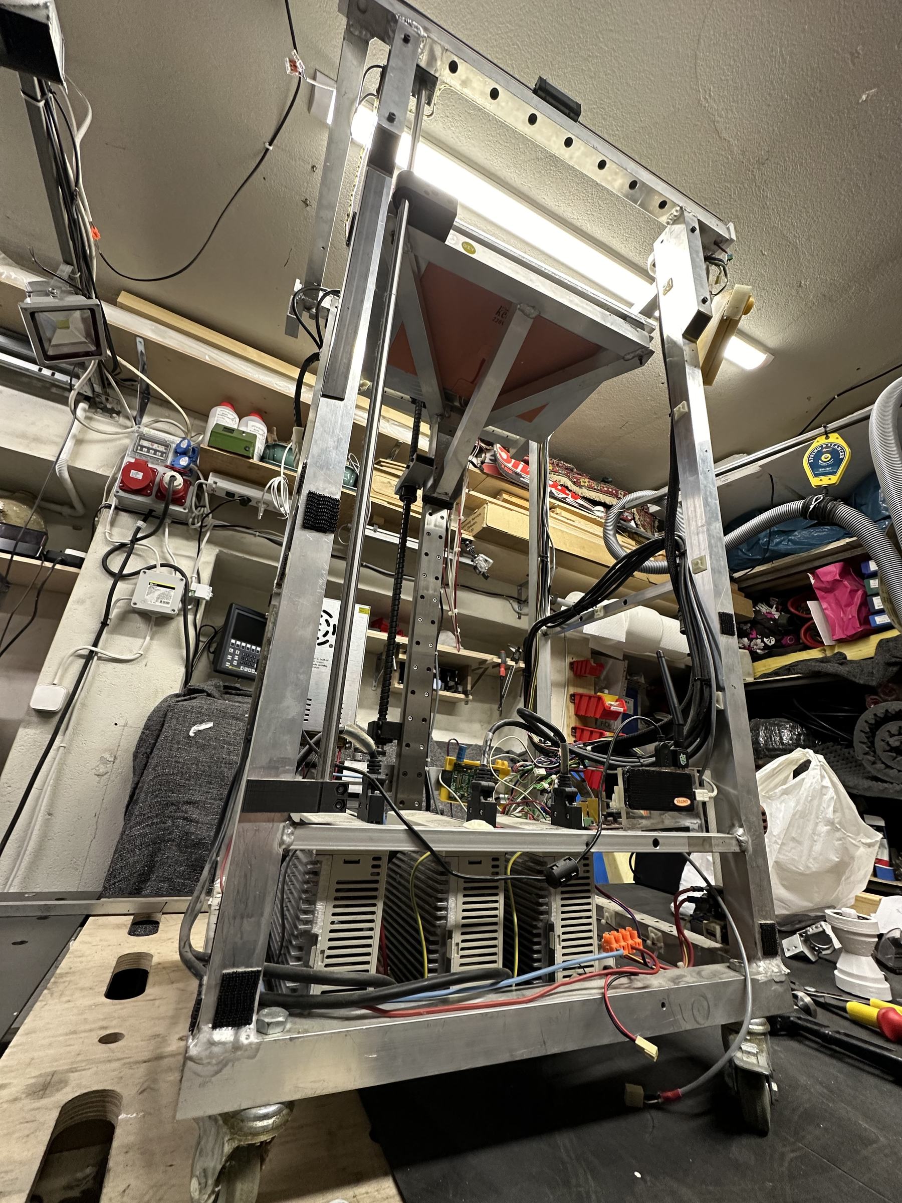
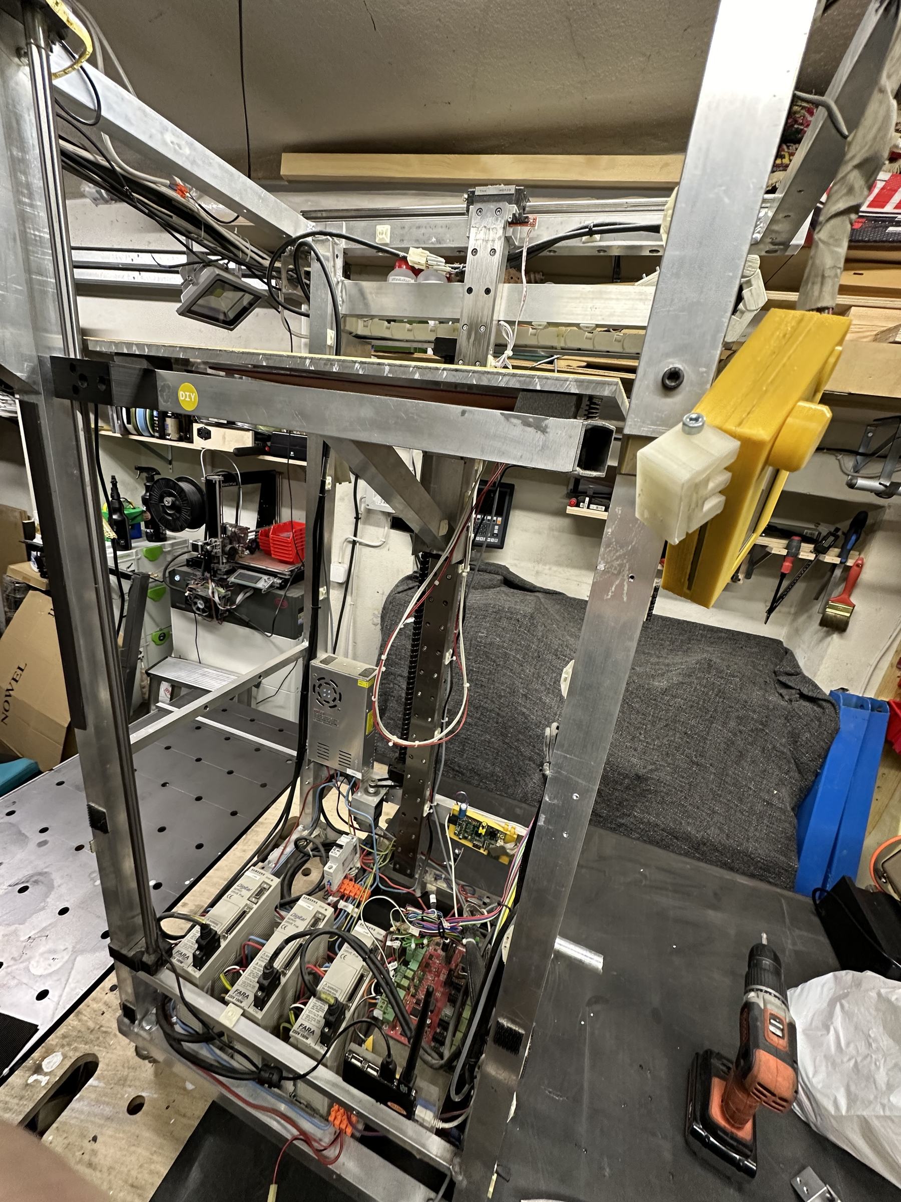
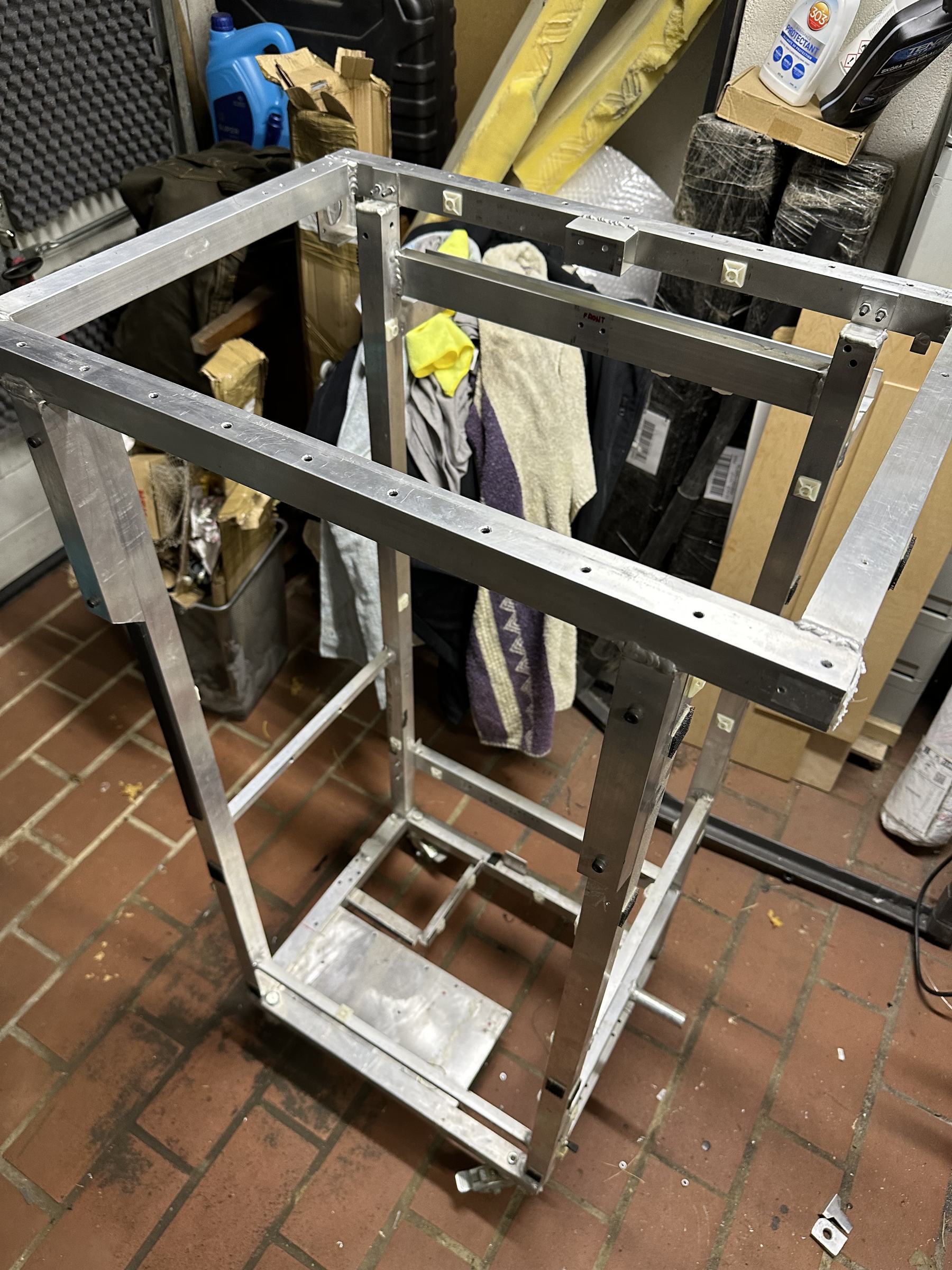
This time, the project started properly in CAD (Fusion 360, to be exact).
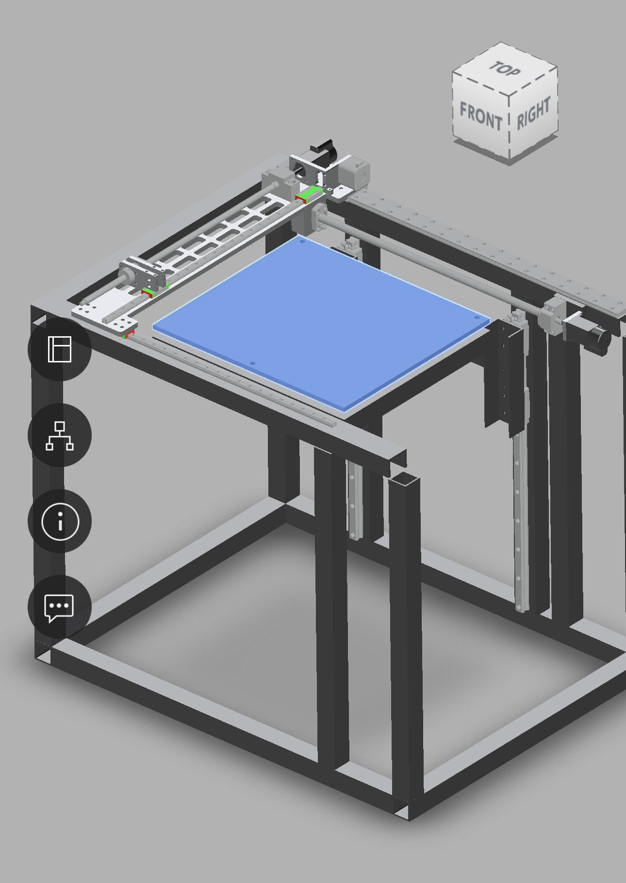
In every printer, the most critical element is the X/Y frame, and any alignment issues there will get transferred to other aspects of the printer, including prints not being square. That is why I chose to CNC-mill the Y-axis out of MIC6 aluminium and start welding and assembly from there. Getting both of the X-axis beams flat took some time to get them milled correctly and then properly flattened. To make things a bit spicier, the beam with a ball screw driving the X-axis movement uses a different linear guide than the other, so their heights differ.
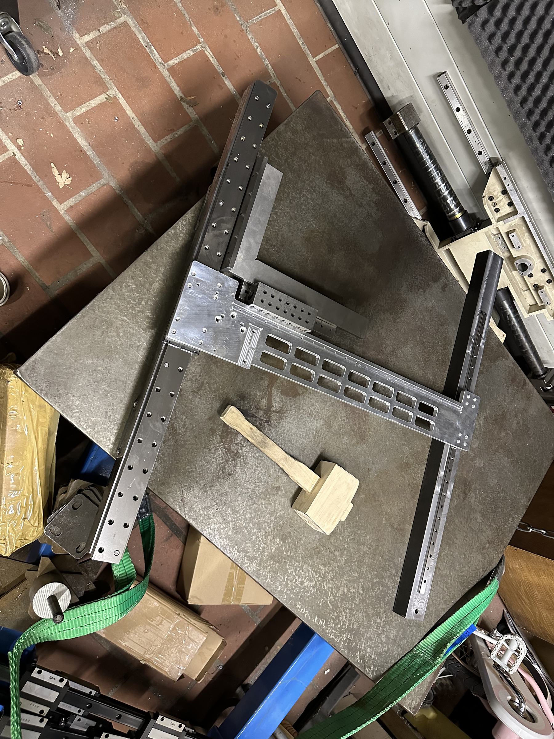
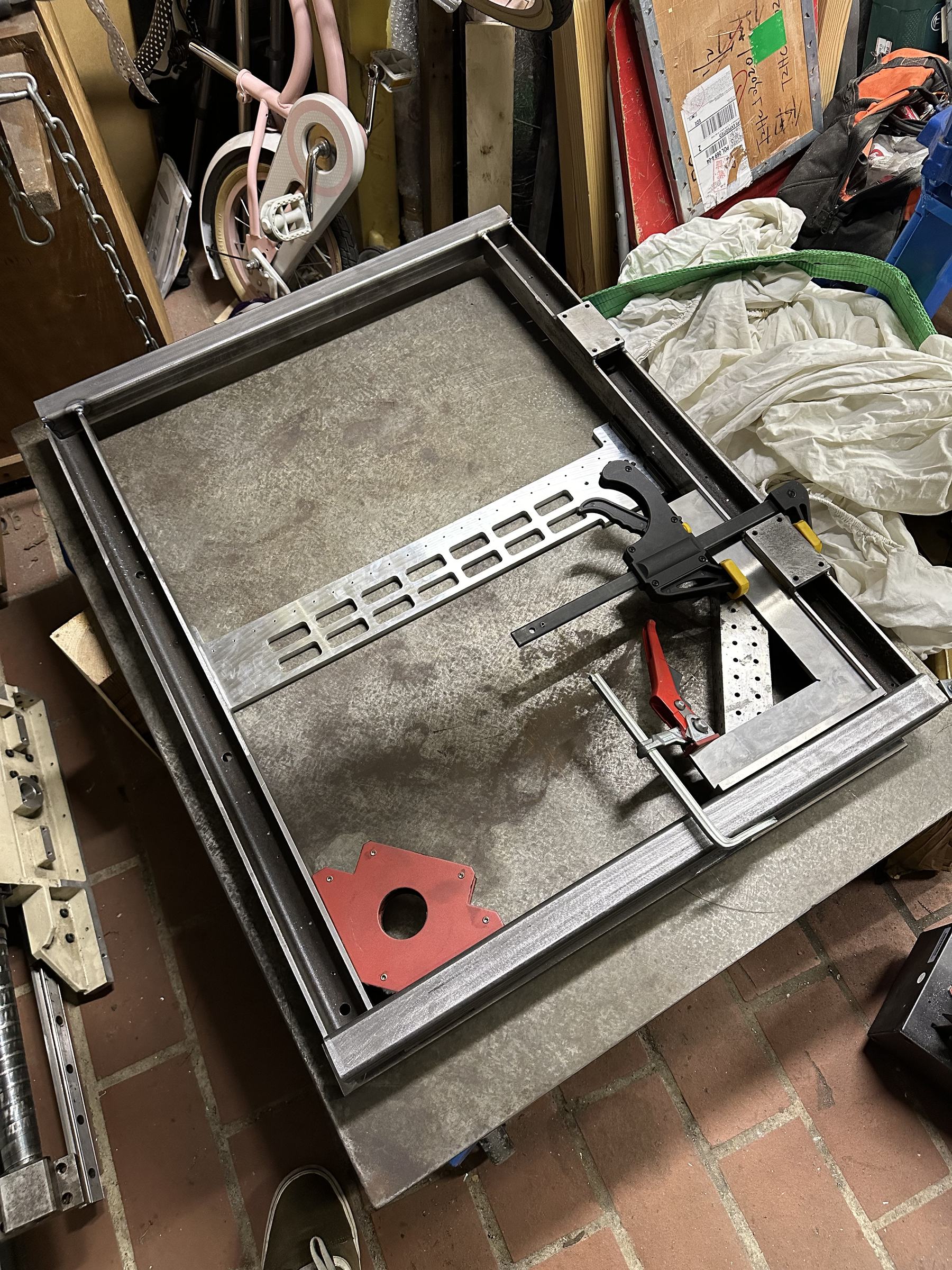
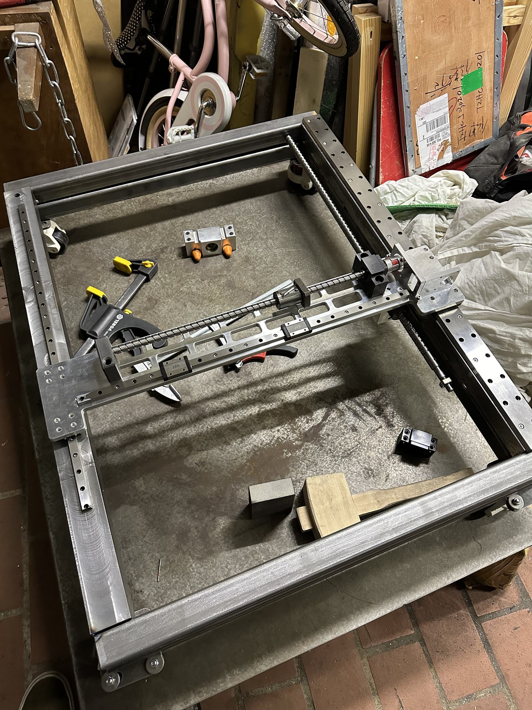
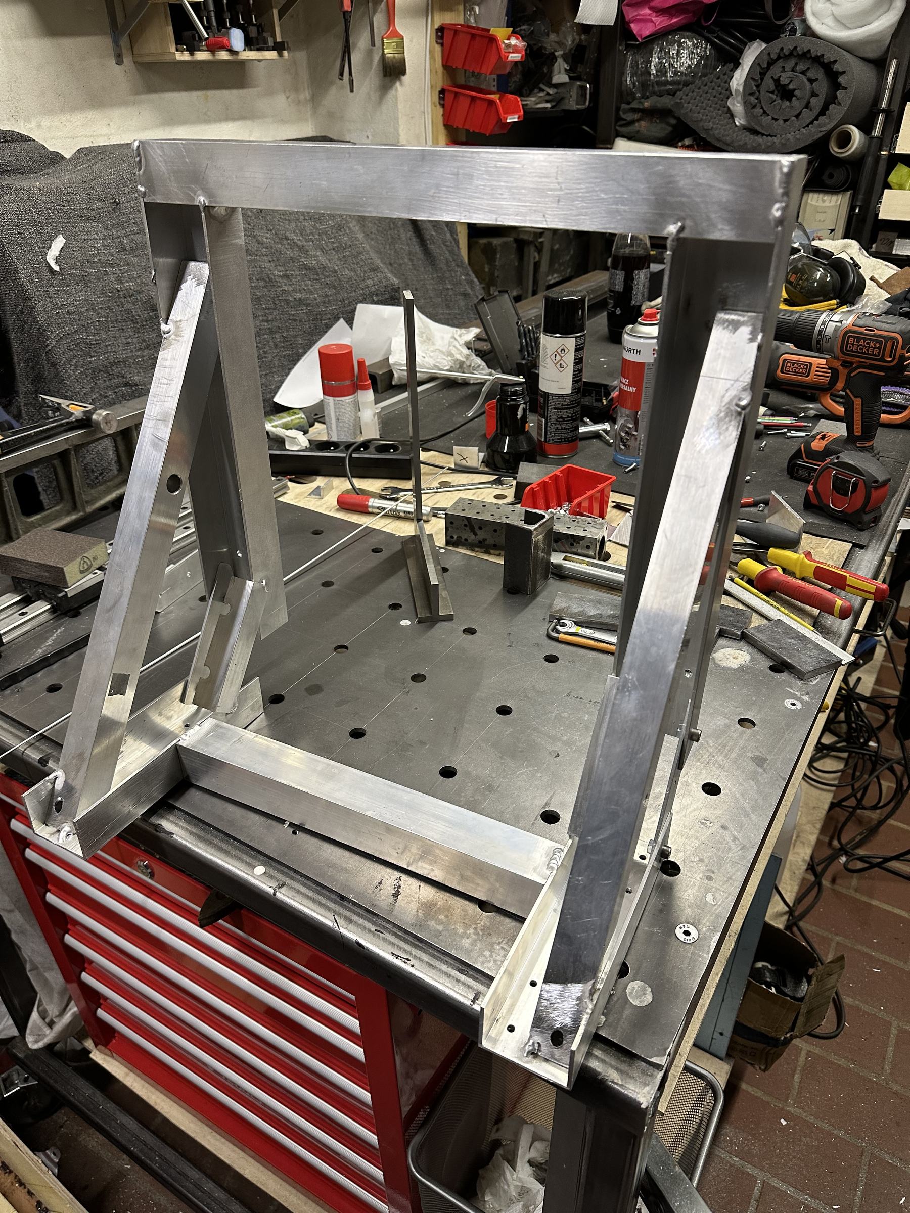
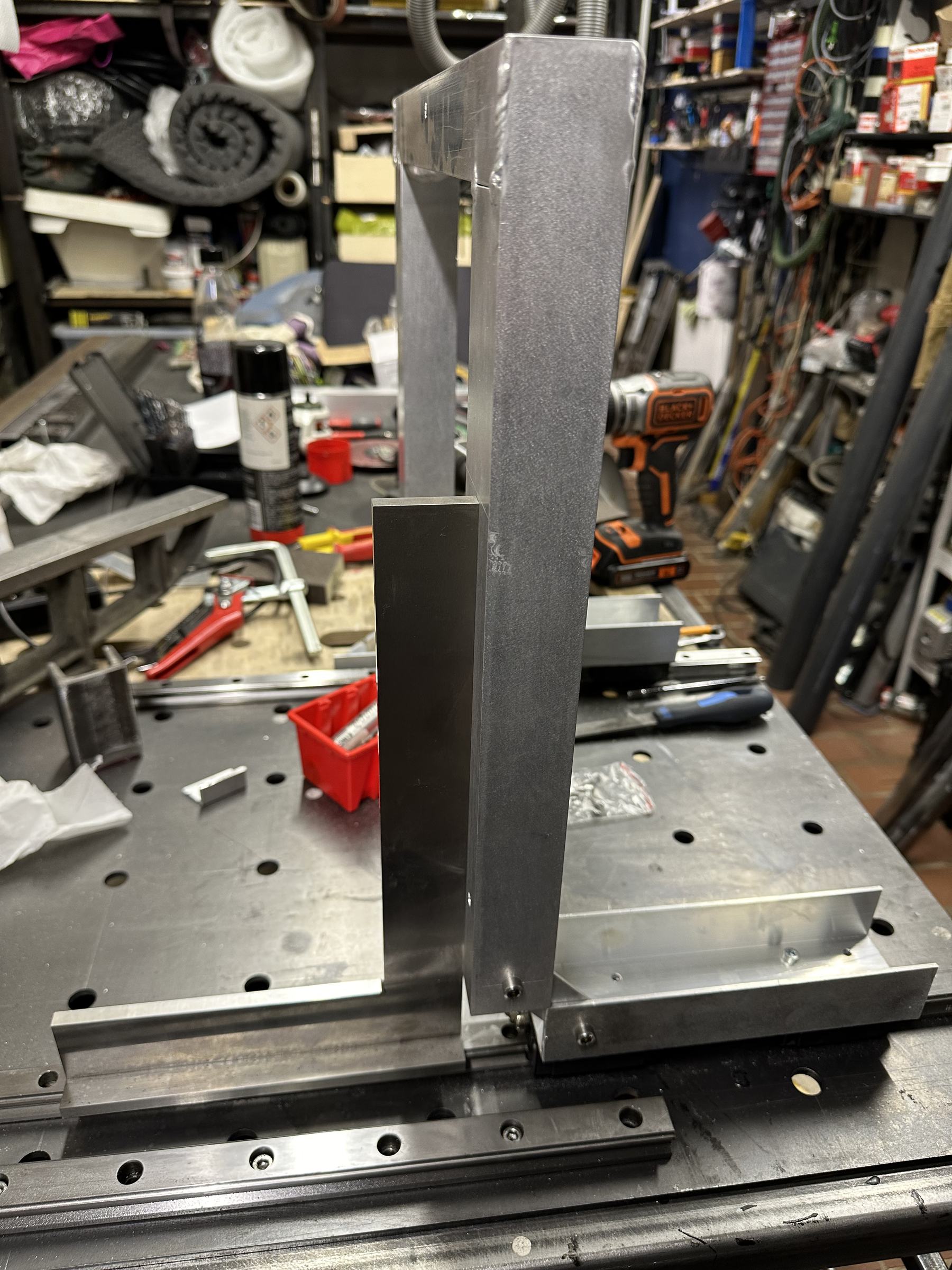
After having fun to get the main rectangle square and not warped due to dumping too much heat with TIG I move to the next thing: getting the Z axis perpendicular to the X/Y. Again more welding, more squaring, and keeping close to my heart "when you can't make it precise at least make it adjustable".
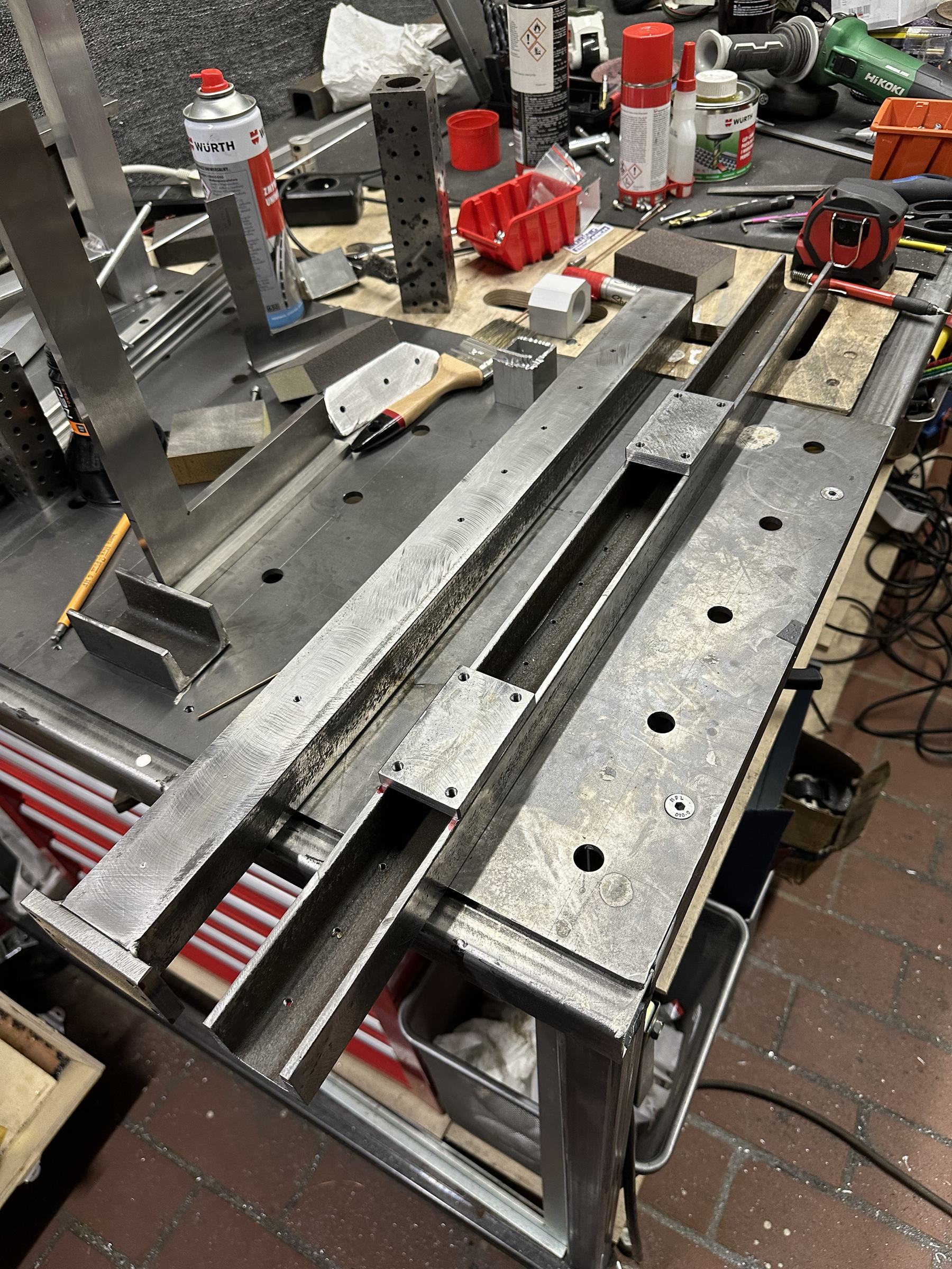
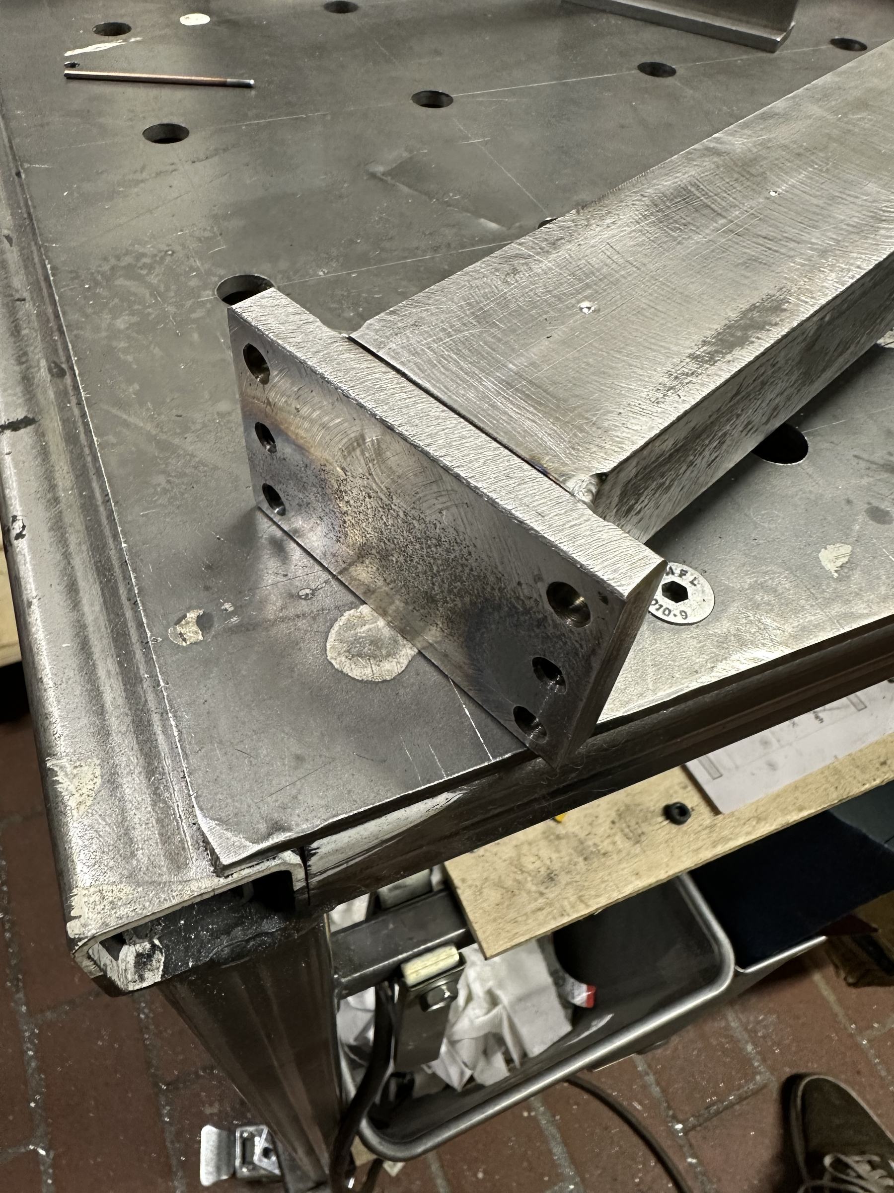
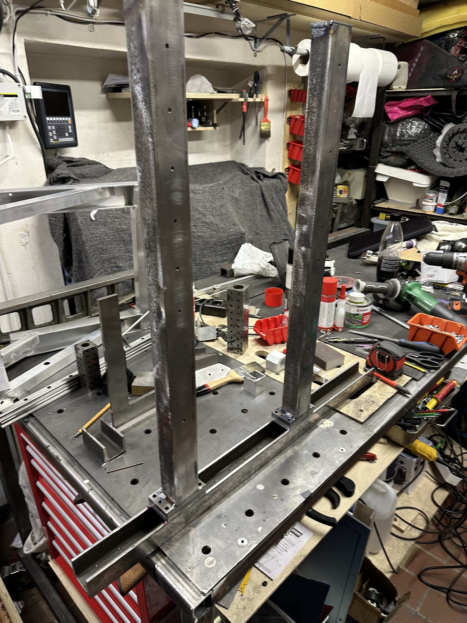
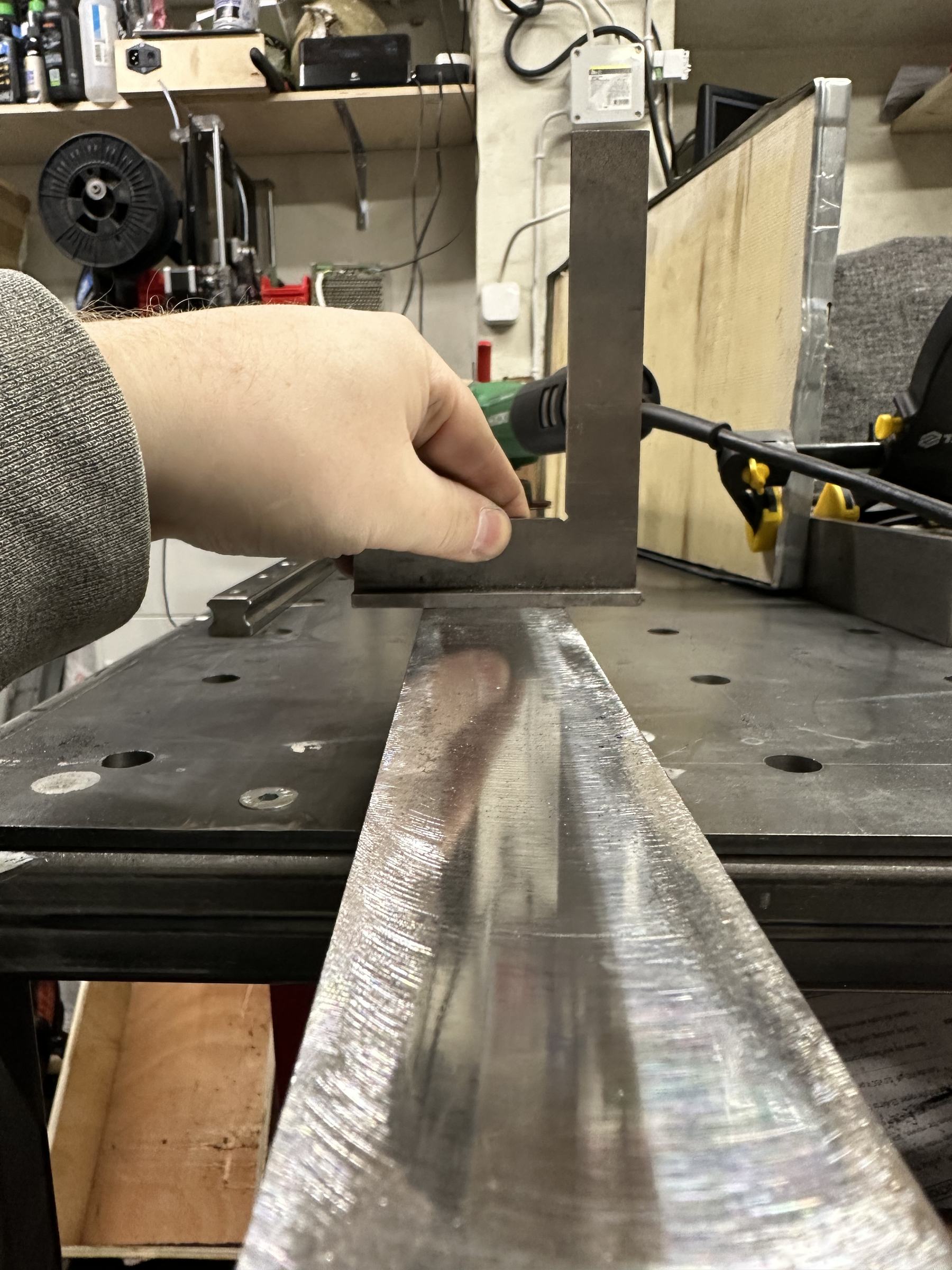
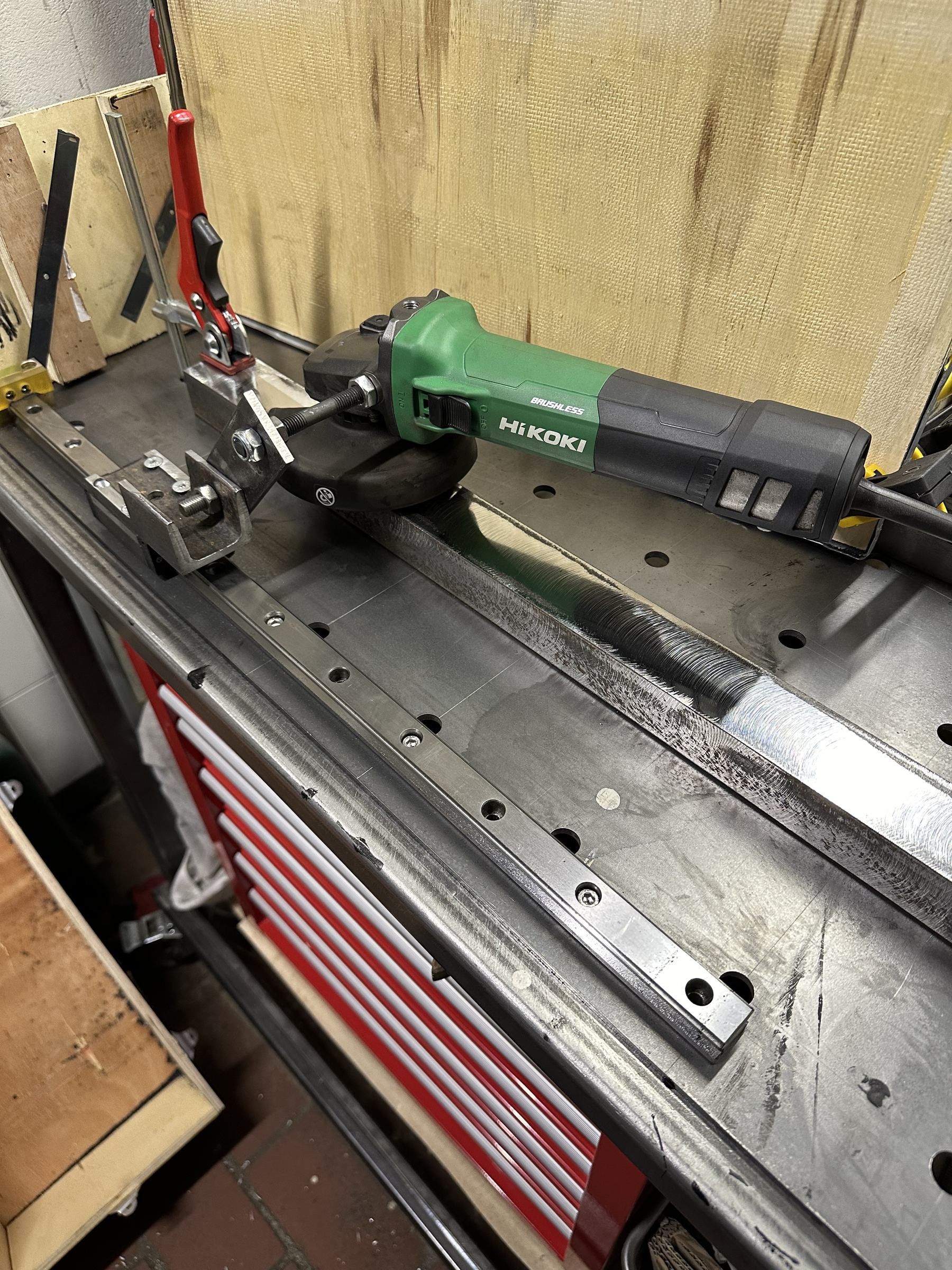
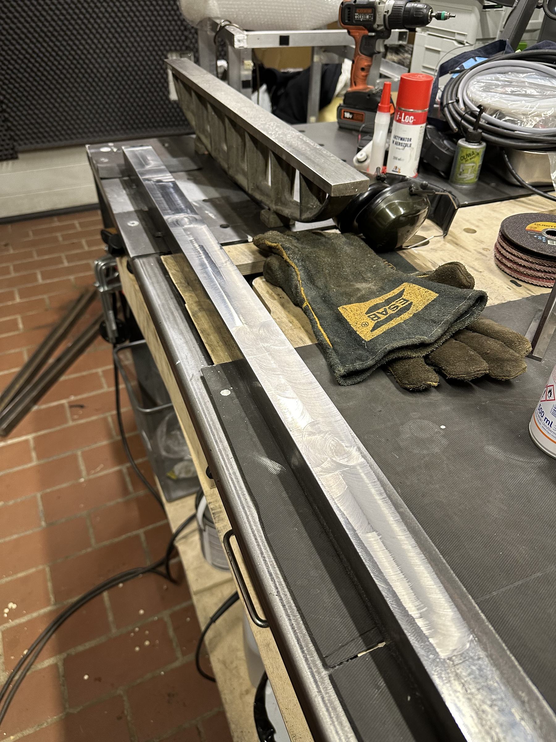
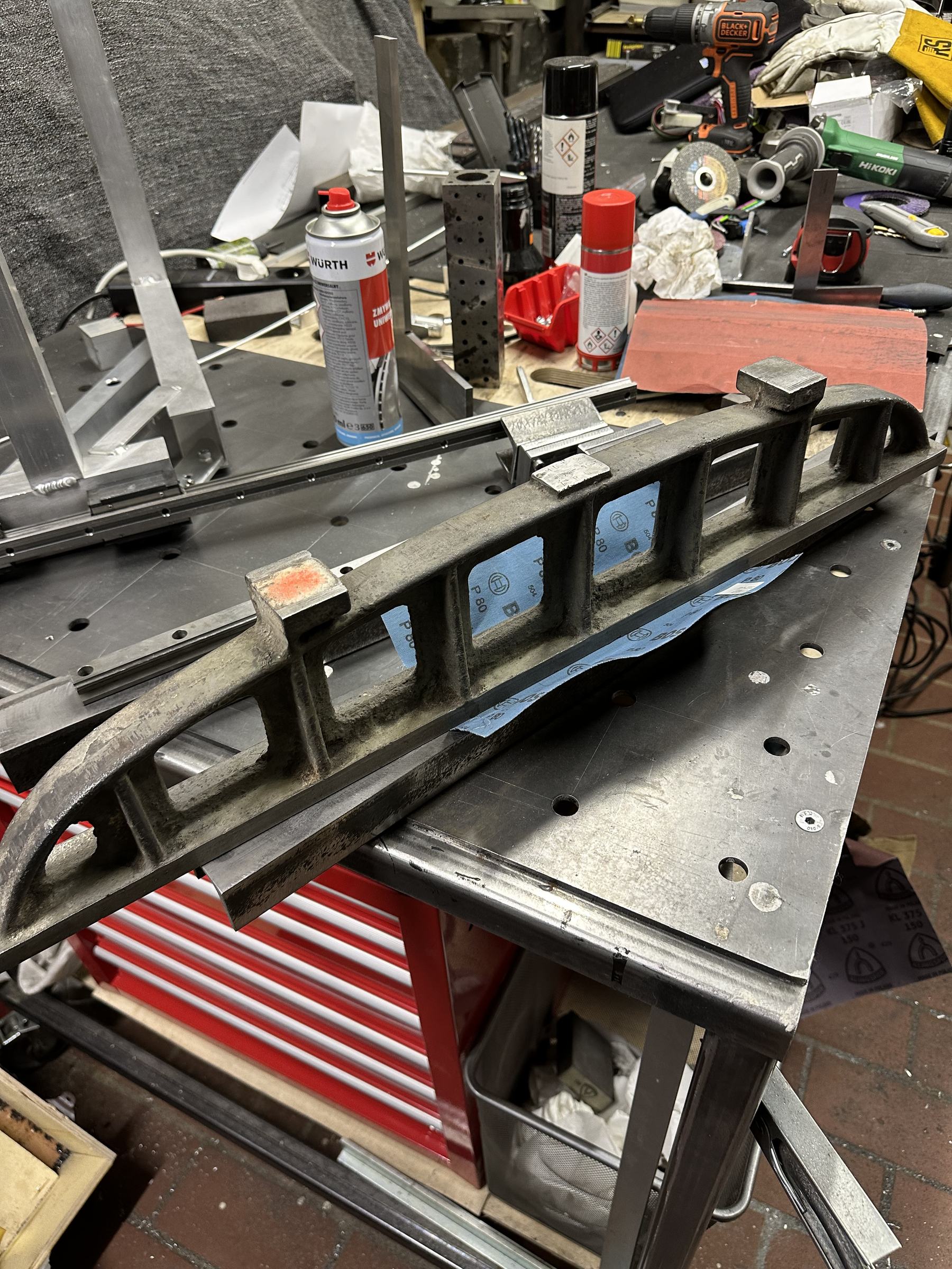
The Z-axis beams, instead of being milled, received a different treatment: they were ground to a decent flatness using a jig. Then I flattened the beams further with sandpaper and a straight edge. No light passed under a "known flat surface".
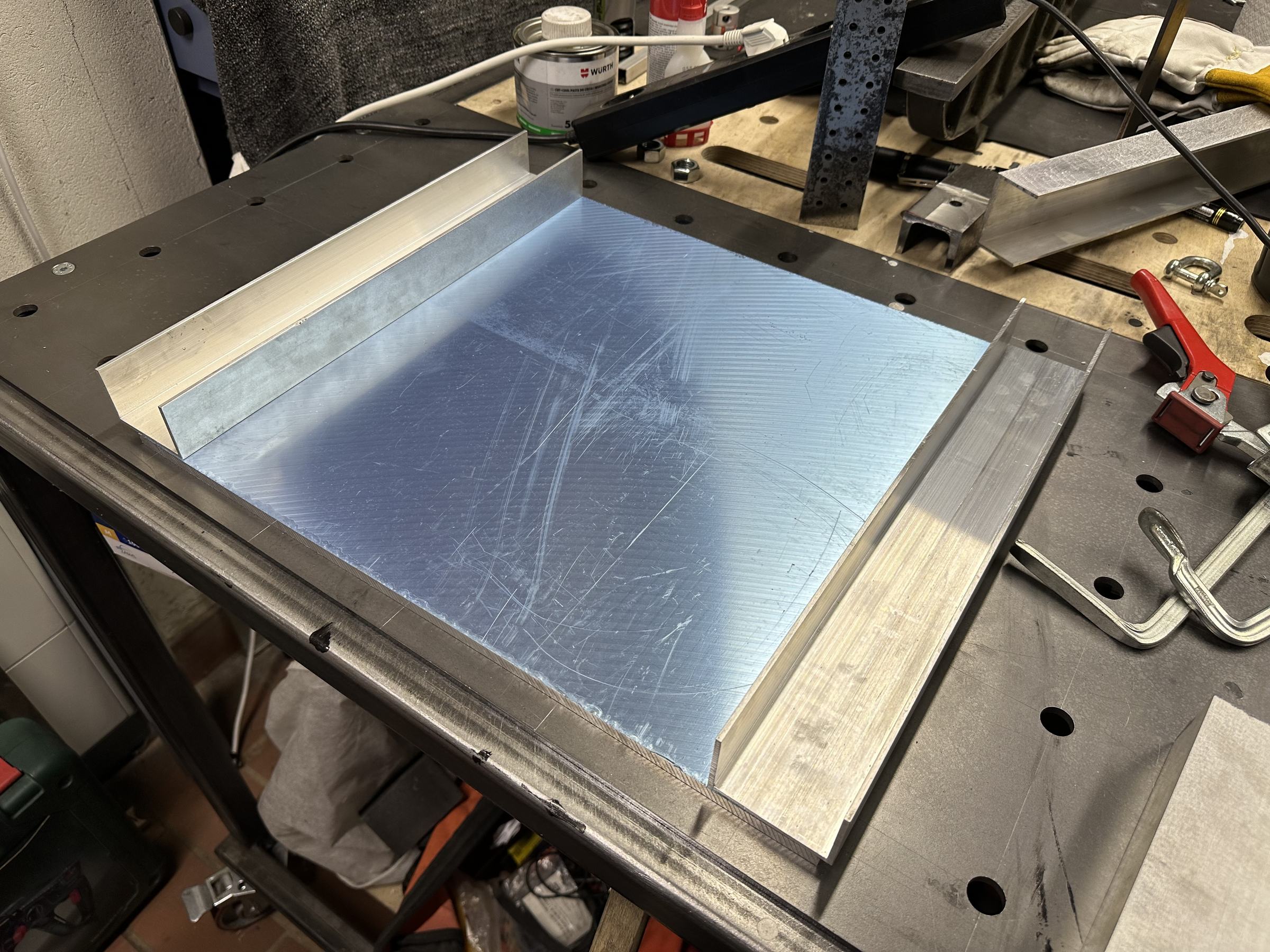
Z axis has a MIC6 10mm plate and is using welded aluminium extrusions to keep it rigid but lighter than a steel frame would weigh.
And that is it for now, more to come.
Contact me
Questions, ideas, or spotted a bug? Send me a note.