by Łukasz Jakóbiec
H-Brigde – Do It Yourself
…if you must to! H-Brigdes are quite basic piece of hardware, steering them is where fun begins. For all those of you who prefer easy solution that just work please look into L293 or L298 which can drive two motors with current up to 1A or
…if you must to!
H-Brigdes are quite basic piece of hardware, steering them is where fun begins. For all those of you who prefer easy solution that just work please look into L293 or L298 which can drive two motors with current up to 1A or 2.5A per motor. Or you can use VNH3SP30TR-E for currents up to 30A.
Little introduction
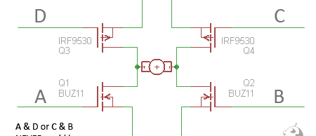
If an H-bridge is a common and basic piece of hardware, why is it so hard to build one that works? There are a lot of answers to this, but the most common are: Some of these errors are easy to fix, like overcurrent is just a matter of doubling MOSFET count. Also, switching them too fast with PWM can be easily overcome by simply dividing the PWM frequency (at least in AVR it is easy). But for a moment, let's just back up from the whole H-Bridge thing with at least 4 MOSFETs. Have you considered using one FET and a relay? If you don’t need rapid direction changes and you wouldn’t miss the braking function, then this easier and cheaper solution is for you. When it comes to handling currents, it is usually limited mostly by MOSFET parameters. Since we can use only one FET, we would choose an N-channel MOSFET. They are faster, handle bigger currents, and there are a lot more of them available. But going back to the H-Bridge, we usually will use both N-channel and P-channel MOSFETs. P-channel FETs are slower when it comes to switching and usually can handle smaller currents. For example FETs used in schematic above uses BUZ11 N channel MOSFET which can handle 30A but the P channel MOSFET IRF9530 can handle only 12A. Remember that this parameter ( the RDS (on)) is for 25C when the IC substrate gets hot, it starts to be more resistive, so the Amperes that can flow are reduced. It is best to assume that we will be using MOSFETs at their 70% to be sure that they won’t blow. And sure they do that quite often. Especially when you switch them wrong ( remember A&D or C&B ?).
- wrong component chosen
- errors in controlling FETs
- over current which is result of wrong components
- too fast switching
Digging deeper
MOSFETs are voltage controlled devices. It means that when you would like to control them from the AVR (or other 5V source), you will have to choose MOSFETs that are logic-level operated. It means that they can work on such a small voltage (Gate voltage). Also you need to know that 5V is not enough to fully open FET. Look at the Transfer characteristic chart; you can see that at 5V it is only open in1/10. This means that the FET is not fully open and its resistance is 10 times higher than when fully open. So if you use 5V and try to run at full load, you will blow your MOSFET. This also depends on the voltage between Drain and Source (Vds). This makes using an N-MOSFET hard at the high side of the H-Bridge (D & C parts). To use them there, we need to use a charge pump to drive the gate higher than +V. It should be driven +V + 10V more then when used on low side. Fortunately, there are specialised ICs for driving N-MOSFETs on the high side (for example, LTC1155). To further add to this little nightmare, the MOSFET Gate is like a capacitor, so to drive it fast you need more current to charge the gate capacitor.
So to sum up:
- N-MOSFET conducts when Gate is at least 5V+ (MOSFET with logic level triggering; when Source is connected to GND, when you connect Source to V+ then Gate must be operated at +V + 5V at least) and has fast fall and rise times
- P-MOSFET conducts when Gate is at GND potential (0V) and are a bit slower than N-channel FETs
Some examples
So now that we have some knowledge lest try some examples. First one is a basic H-Bridge made from N-MOSFETs and P-MOSFETs utilising the TC429 high-current MOSFET driver and some NAND gates to ease interfacing with AVR. This design doesn’t provide a STOP function. Using TC429 enables us to add MOSFETs to simply extend the current we can work with. So in this example, we can work with 15A when we provide cooling to the circuit. When we double the FET count, we will be able to work with 30A thanks to high-current drivers. If you can’t find TC429, you can use another MOSFET driver with an inverted output or move the inverting gates IC1A and IC1B to low-side drive. Remember to always add protection Schottky diodes. When you stop providing the motor with current, it will behave like an inductor trying to sustain current flow. If you use diodes, they will provide a way for the voltage spike to dissipate instead of destroying MOSFETs.
Contact me
Questions, ideas, or spotted a bug? Send me a note.