by Łukasz Jakóbiec
A Neato XV LIDAR connection verification (with tool)
A spinning laser rangefinder salvaged out of a robot vacuum: 360 readings a revolution over a plain serial port. Here is how I wired one up, the one-character bug in the code almost everybody copies, and a browser tool that reads the sensor over Web Serial so you can check yours in a minute.
The Neato XV series robot vacuums have a spinning laser rangefinder on top, and when one of those vacuums dies the scanner usually does not. It gives 360 distance readings a revolution, one per degree, about five times a second, over a plain serial port at 115200. For indoor robot work that is a great deal of sensor for very little money, which is why these things have outlived the vacuums they came in by more than a decade.
I wired one up. It works. Almost none of the time went on the wiring, and a good part of it went on a single character in the code that nearly everybody copies.
TL;DR: Open the XV-11 lidar tool
Two connectors, and only one of them does what you expect
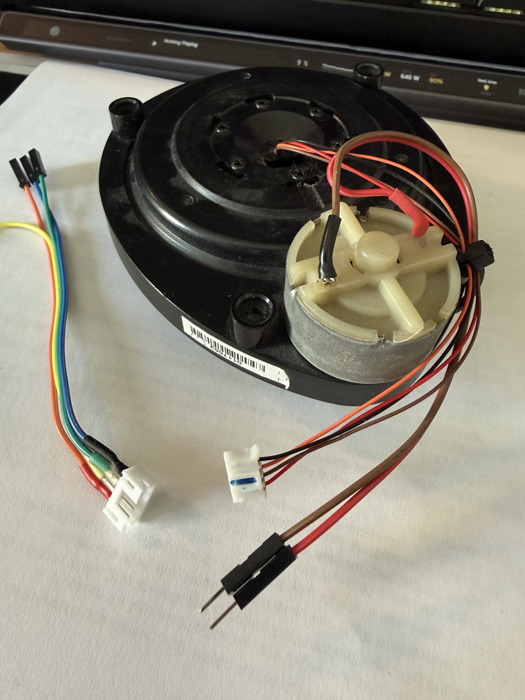
The puck has two cables. The four-pin one carries logic power and data. The two-pin one is nothing but the motor.
- Red, +5 V, logic power. Around 45 mA idle and 135 mA turning.
- Brown, LDS_RX. Leave it unconnected. The sensor accepts no commands, so there is nothing to send it.
- Orange, LDS_TX. The only wire that carries data. It is 3.3 V logic, which a 5 V adapter reads without complaint.
- Black, ground, shared with whatever drives the motor.
Wire colours move around between revisions of the module, so confirm yours before applying power rather than trusting that list.
Here is the part that catches people out. There is no command to start the motor. Nothing you send down the serial line will make it turn, because the sensor does not listen to anything. In the vacuum, the robot's mainboard drove the motor and ran the speed control. On your bench that is your job. A stationary XV-11 produces nothing useful, and from the software side a stationary one and a mis-wired one look identical.
The mistake I made with the motor
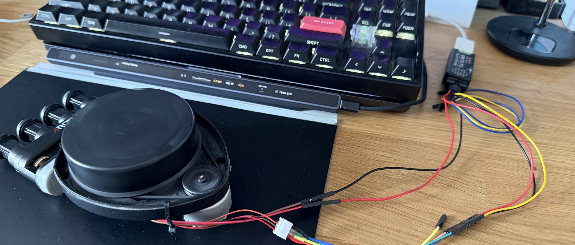
I ran the motor straight off the 3.3 V output pin of my Waveshare USB-to-serial adapter. It spins. It spins at about 310 rpm, which is very nearly right, and the data coming back is clean.
That pin on an FT232RL is rated 50 mA. The XV-11 motor wants somewhere between 60 and 100 mA once it is turning. A CP2102 gives you around 100 mA in total, and the chip itself eats a good fraction of that.
The fact that it works is exactly what makes it a bad idea rather than an obvious one. Nothing fails loudly. The regulator runs over its rating and gets warm, the rail sags under load, and the motor speed wanders in a way that is hard to attribute to anything in particular. If you are building one of these, give the motor its own supply at about 3V and share only the ground. I haven't done that yet, because I was more worried about LIDAR not sending reasonable data.
Getting bytes out of it
115200, 8N1, no flow control, receive only. On macOS, open the cu. device and not the tty. one. The tty node blocks on open waiting for carrier detect, and a serial port that hangs for ever when you open it looks precisely like a sensor that is not there.
$ ls /dev/cu.usbserial-*
/dev/cu.usbserial-AB0LH7J3
The packet
Twenty-two bytes, ninety of them to a revolution, four readings in each. That is 360 readings of one degree.
FA <index> <speed_L> <speed_H> [4 readings x 4 bytes] <crc_L> <crc_H>The index byte runs 0xA0 to 0xF9, and the angle of the first reading in a packet is (index - 0xA0) * 4. Speed is 16-bit little endian, RPM times 64. Each four-byte reading goes:
- byte 0: distance, bits 7 to 0
- byte 1: bit 7 no-return, bit 6 strength warning, bits 5 to 0 distance bits 13 to 8
- bytes 2 and 3: signal strength, little endian
One practical detail that is not in the protocol anywhere: my puck turns clockwise, and the packet index advances with the rotation, so on a plot seen from above the angle advances clockwise too. Get that backwards and you draw a mirror image of the room, which is entirely believable and completely wrong.
The one-character bug
Distance is fourteen bits. Byte 0 gives the low eight, and the low six bits of byte 1 give the rest, the top two bits of that byte being the flags. So the mask is 0x3F.
The tutorial I started from, and a fair number of the samples you will find elsewhere, mask it with 0x1F. That keeps thirteen bits instead of fourteen. The prose on that same page says bits 5 to 0, which is right. The code underneath it says 0x1F, which is not. Both were sitting there together.
The effect is that everything past 8191 mm wraps around. A reading of 9000 mm comes back as 808 mm. Not as an error, not as a zero, not as anything you would spot in a log: it comes back as a solid object sitting right in front of the robot. Put that into obstacle avoidance and you get a machine that stops dead for a wall nine metres away, and you spend an evening blaming the motor controller.
The reason the bug survives being copied is that it only bites past 8.1 m, and an XV-11 is not much use past about 6 m anyway. Most of the time it is invisible. That makes it worse, not better.
The checksum nobody prints
The tutorial gives the packet layout and then leaves the checksum out entirely, which is a shame, because it turns out to be the single most useful thing in the whole protocol. I took it from getSurreal's XV Lidar Controller and cross-checked the bit masks against the rohbotics ROS driver, rather than trusting any one source.
Take the first twenty bytes as ten 16-bit little-endian words. Shift the accumulator left by one and add each word in turn. Then fold it: add the low fifteen bits to whatever fell off the top, and mask to fifteen bits again.
def checksum(head):
    chk = 0
    for i in range(0, 20, 2):
        chk = (chk << 1) + (head[i] | (head[i + 1] << 8))
    return ((chk & 0x7FFF) + (chk >> 15)) & 0x7FFF
Why I check the link in five stages
"No data" is not a diagnosis. It has at least four causes with four different fixes, and I wanted something that told me which one I had instead of shrugging. So the check runs in order and stops at the first thing that fails.
- Port. Does it open, or is another program holding it?
- Bytes. Is anything arriving at all? Nothing here means no power, no TX wire, or a motor that is not turning.
- Framing. Is there a 0xFA followed by an index in range?
- Checksum. Are these actually packets?
- Health. Speed, coverage, and how many readings are usable.
Stage four is the one that earns its place. At the wrong baud rate you still get a healthy stream of bytes, and 0xFA turns up in random data about once every 256 bytes, so stages two and three will pass cheerfully on pure noise. The checksum is the only stage noise cannot fake. If it reads 100%, you are looking at a lidar. If it reads 4%, you are looking at noise, whatever the byte counter says.
One more thing about reading the stream: do not split it on 0xFA. That byte occurs inside distance data, so framing on it alone gives you packets that look plausible and are wrong. Require the start byte, an index in range and a good checksum, and when the checksum fails advance by one byte rather than by a whole packet. Skipping twenty-two bytes after a bad checksum is how a reader ends up permanently out of step with a stream that is otherwise perfectly fine.
There is a speed limit, and it is arithmetic
A revolution is 90 packets of 22 bytes, so 1980 bytes. At 115200 8N1 the line carries 11520 bytes a second. Divide one by the other and the sensor cannot transmit a complete revolution above 349 rpm.
At the nominal 300 rpm the link is already 86% full. Mine runs around 310 and sits at 94%. That is worth knowing before you start winding the motor voltage up hoping for a faster scan, because past 349 rpm you do not get a faster scan. You get one with holes in it.
The thing I have not solved
My unit sends about 3% of its packets with an index that breaks the sequence, and about 19% reporting a rotation speed a long way from the real one. Every one of those packets has an intact checksum, and USB serial is a reliable ordered stream that cannot invent or reorder frames, so the sensor is sending them that way. That much is settled.
Why is not. There is one clue I like. The stray speeds are 242.2 and 404.7 against a true 303.5, and those are exactly 4/5 and 4/3. A motor cannot change speed by a third and back again inside a few milliseconds, because inertia will not let it. Firmware timing rotation over a count of intervals and occasionally miscounting by one gives you precisely those two ratios, and the same miscount would corrupt the packet index alongside it. That is a hypothesis with a pleasing shape and no proof.
The obvious suspect is the motor supply from earlier. A current-starved motor stuttering would be a reasonable trigger. It is a falsifiable test and I have not run it: give the motor its own supply and see whether the stray rate falls. If it does, that was it. If it does not, the sensor is doing it on its own and I am back to guessing.
What the hardware found that my tests did not
I wrote the decoder against a synthetic scan first, and it passed everything I threw at it. Then I pointed it at the real sensor and it reported 51 revolutions in five seconds from a puck turning at 303 rpm, where the truth is 26. The stray packets above look like the index wrapping round, so every revolution was being cut in half.
Separately, the plot title read 403 rpm on a sensor holding a steady 303, because it took the speed from the last packet of the revolution and the last packet was sometimes a stray one. Taking the median across the revolution fixed that.
The third was subtler, and I only caught it because the synthetic source has a known answer. The tool reported 94 packets per revolution from a generator emitting exactly 90. It was dividing every packet it had ever seen by the number of completed revolutions, which folds the revolution currently in flight into the average. Against real hardware that is indistinguishable from the genuine excess the stray packets cause, and it had already gone into my notes as a measured fact before the demo caught it.
All three are the same lesson in different clothes. A test that only ever runs against data you generated yourself will agree with you.
The tool
All of the above is in one HTML file that talks to the sensor from the browser over Web Serial. Nothing to install, nothing to build, nothing to download. Chrome, Edge or Opera on a desktop; Safari and Firefox do not implement Web Serial.
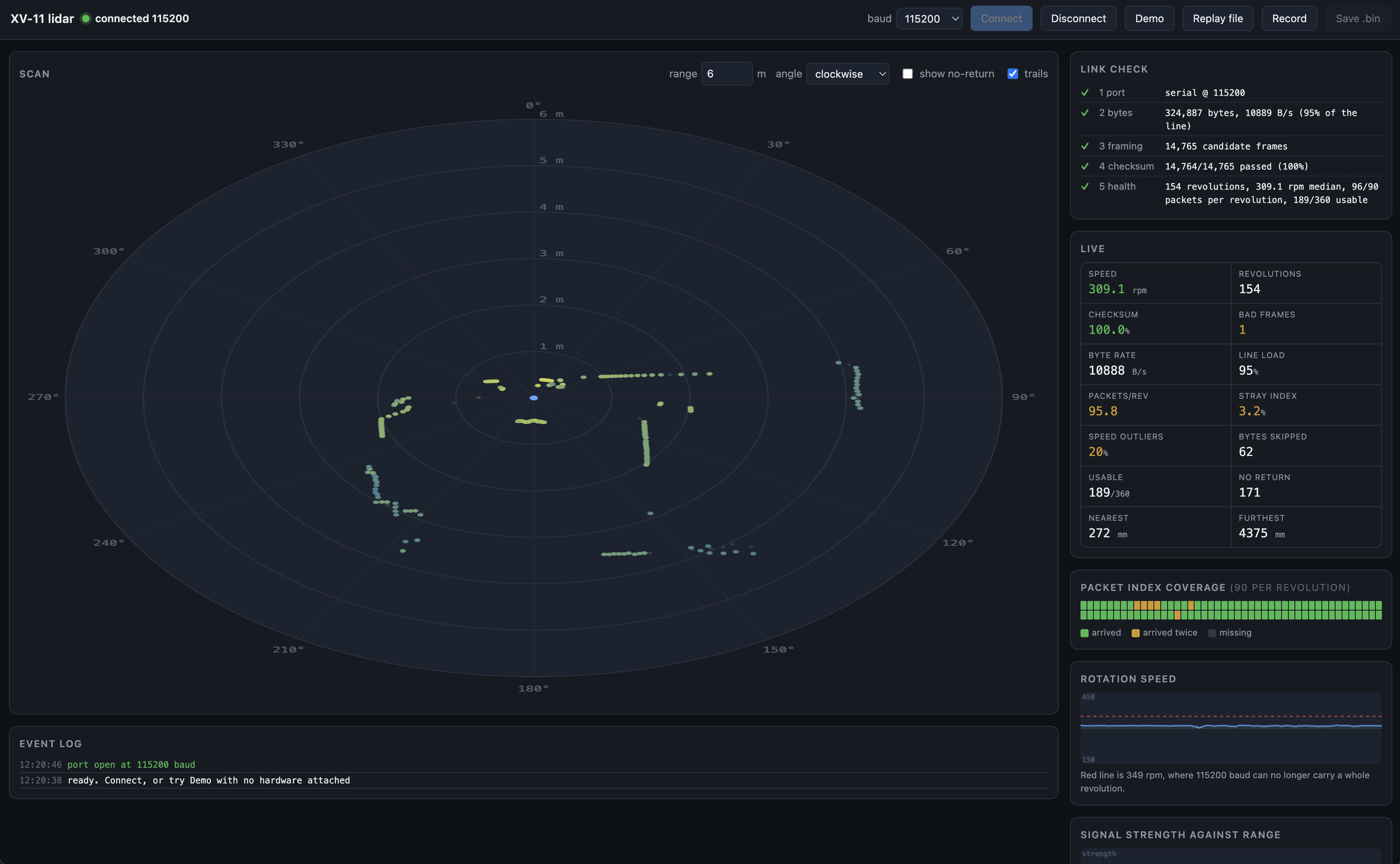
It draws the scan as a polar plot you can hover over to read a bearing and a range. Beside it are the five stages, a live panel of counters, a strip showing which of the 90 packet indices arrived and which arrived twice, a speed trace with the 349 rpm ceiling marked on it, a signal-strength-against-range scatter, and the last packet in hex with its fields picked out in colour. There is a Demo button that synthesises a room, so you can see the whole thing working with nothing plugged in at all, a Record button that writes the raw bytes to a file, and a replay for reading one of those back afterwards.
A serial port opens exclusively, so close anything else that is holding it first.
Contact me
Questions, ideas, or spotted a bug? Send me a note.