by Łukasz Jakóbiec
Reviving a Form 3B: A Shorted Capacitor Under the PMIC and a 169-Ball Reball
A second printer, a Form 3B, stopped working after a resin spill. The fault was a short on the computer module, under its power management chip. This is how I found it, and what it took to put the chip back.
The Form 3+ series was about a printer whose software had gone bad. This one is a hardware fault on a different printer, so it gets its own post.
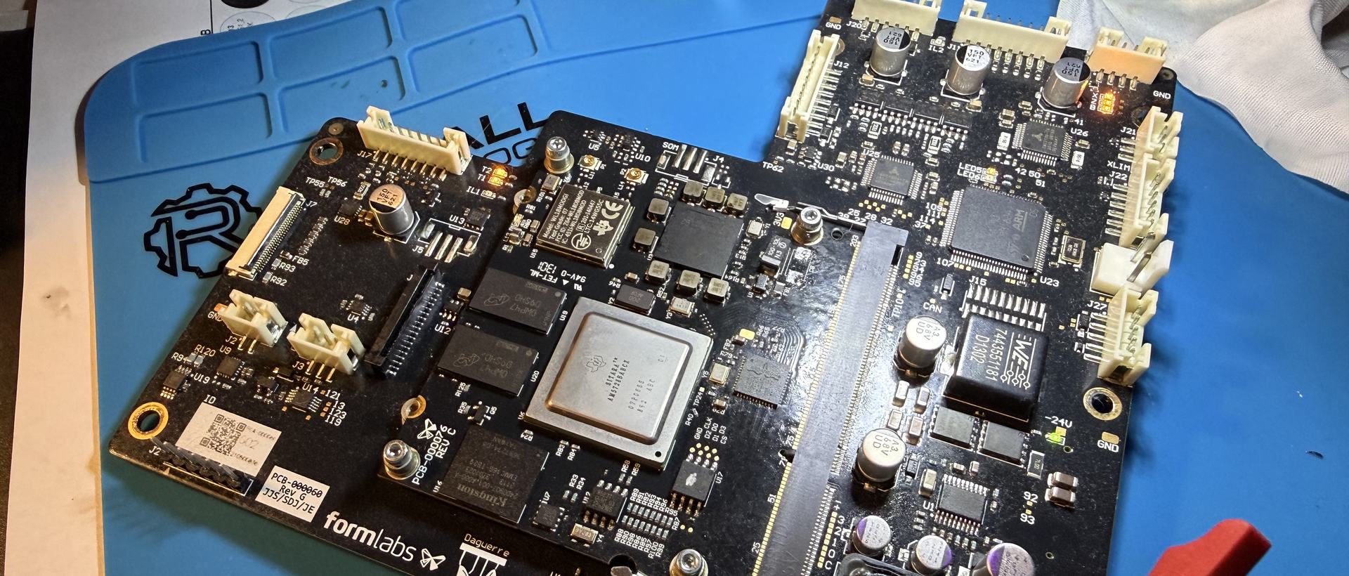
The second printer is a Form 3B. After a resin spill it would not start at all. The cause turned out to be a short circuit on the SOM, the small computer module that plugs into the printer's main board. The short was under the power management chip (the PMIC), which is a ball grid array part with 169 solder balls underneath it and nothing you can reach with a probe.
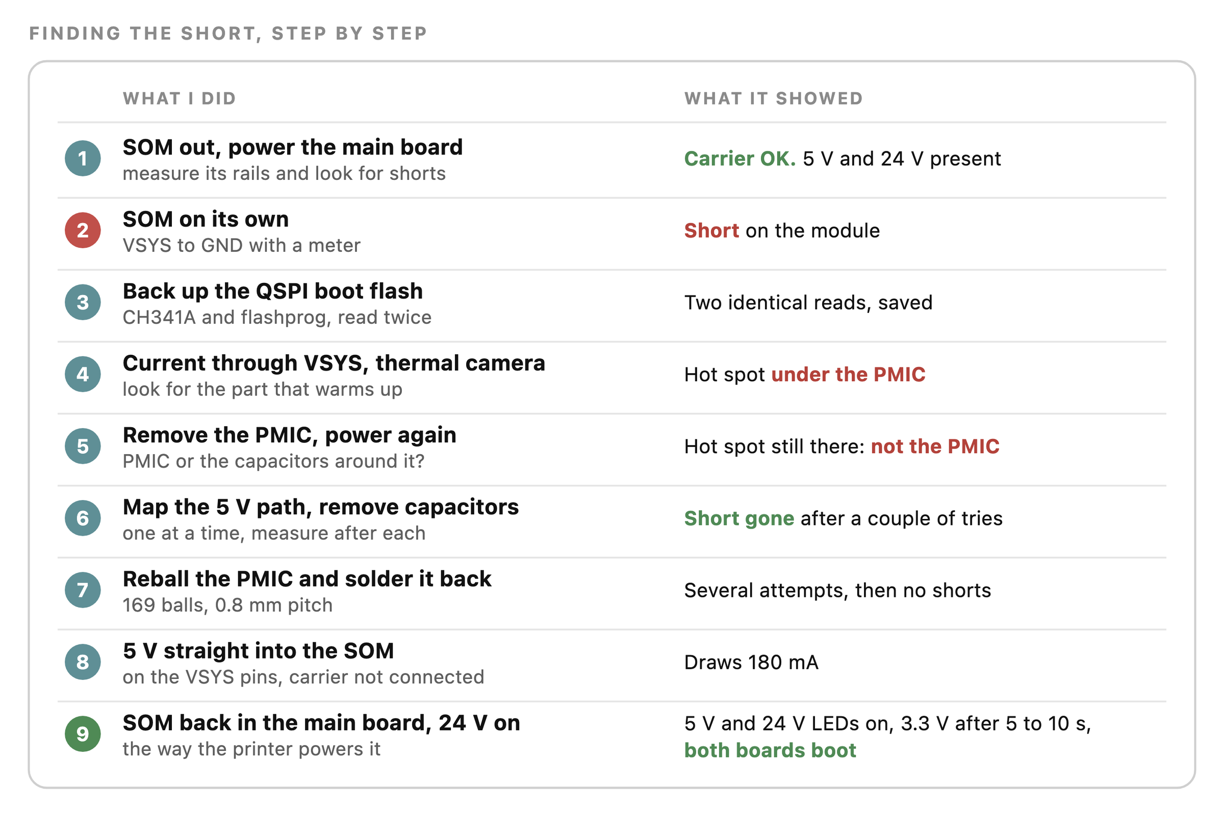
Below is the order I did things in: clean the resin out, work out whether the fault is on the main board or on the module, find the hot spot with a thermal camera, take the PMIC off, find the bad capacitor, check the PMIC itself, then reball it and fit it again. I also made two reference sheets along the way, one for the module's edge connector and one for the PMIC's balls. Both are linked as PDFs below.
Clean the resin out first
When I took the printer apart, it was obvious that there had been a resin spill that was never fully cleaned up. The resin had got into the main board and the SOM.
So before measuring anything, I cleaned the whole printer with IPA (isopropyl alcohol), then cleaned every board and let them dry. I removed most of it, but some resin is still inside the SO-DIMM slot the SOM plugs into.
Main board or module?
The first question with any dead board that has a plug-in module is which half is broken. On the Form 3B the SOM sits in a 204-pin SO-DIMM socket on the Formlabs main board (the carrier), so it comes out without any soldering.
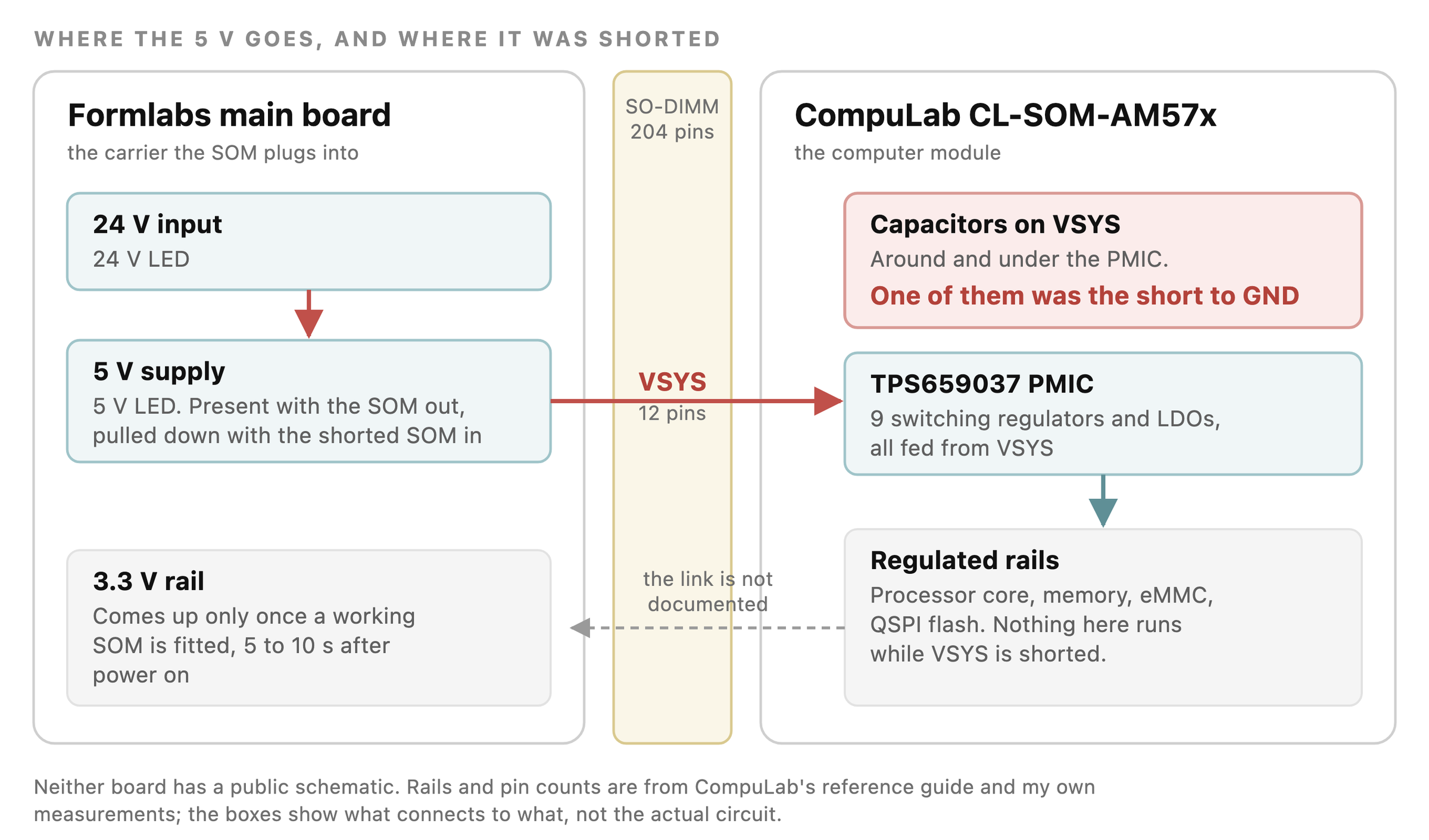
- SOM removed: the carrier had no shorts, and both its 5 V and 24 V rails were present. That matches my working Form 3+. The carrier's 3.3 V rail only comes up once a working SOM is fitted, so its absence here says nothing.
- SOM fitted: neither 5 V nor 3.3 V came up.
- SOM on its own: VSYS, the module's 5 V input, measured as a short to GND: 0.34 ohm.
So the carrier was fine and the module was pulling its 5 V input down to ground. The diagram shows where that 5 V goes.
The module's edge connector
The SOM is a CompuLab CL-SOM-AM57x, built around a TI Sitara AM57x processor. CompuLab publishes a reference guide for it, but no schematic of the module itself, and Formlabs publishes nothing about its carrier.
The reference guide does list every pin. VSYS is on 12 pins: 10, 28, 46, 64, 78, 96, 114, 132, 150, 168, 186 and 204, all even, so all on the same face of the module. GND is on 11 odd pins (1, 19, 37, 55, 71, 87, 105, 123, 141, 159, 177) plus AUD_GND on 195. CompuLab recommends 4.2 to 5 V on VSYS, with 6 V as the absolute maximum.
To have that on one page, I drew the connector with both faces, VSYS in red and GND in black, and the signal on every other pin.
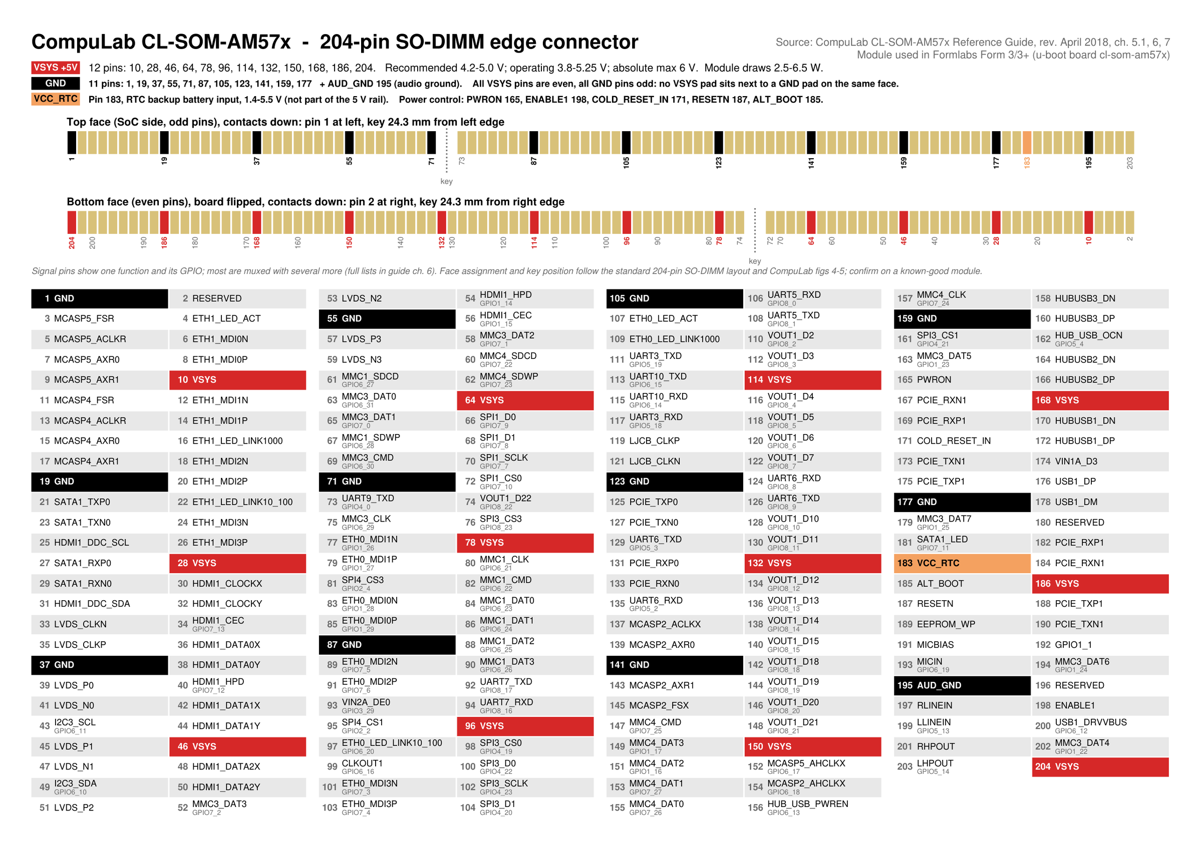
CL-SOM-AM57x edge connector pinout — cl-som-am57x_pinout.pdf
The PMIC
Most of the module's rails come from a TI TPS659037 PMIC fed from VSYS. It is a 12 x 12 mm nFBGA with 169 balls at 0.8 mm pitch. Nine switching regulators each take their input straight from the system supply, so a failed regulator inside the chip is one way to get a dead short from VSYS to GND. A failed capacitor next to it is the other.
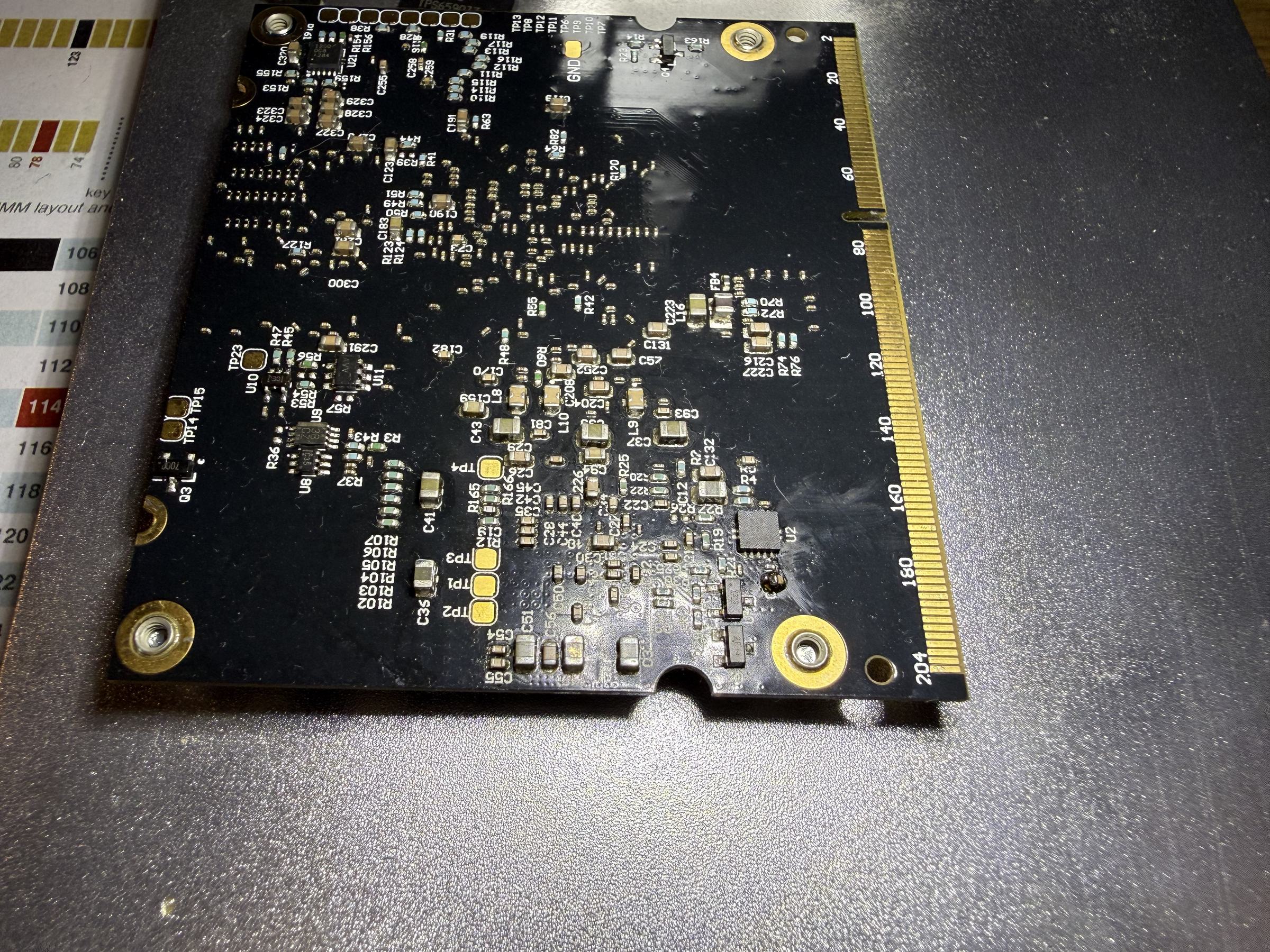
The PMIC is not the only regulator on the module. There are two separate LDOs as well, and VSYS feeds them too:
- a TPS74801, 3.3 V, at the bottom of the board. It delivers up to 1.5 A and has an enable input and a power good output.
- a smaller TPS793xx at the top of the board, next to two capacitors. It delivers up to 200 mA.
The TPS74801 is on the bottom of the module:
TI's datasheet shows the ball map from the top. When the chip is off the board and you are looking at the balls, or at the pads it came off, everything is mirrored. I redrew it as seen from below, with the supply inputs in red, ground in black and the switch nodes in blue. Which of the LDO inputs CompuLab tied to VSYS is not documented, so those are marked separately.
I made this sheet for a specific job: checking the PMIC itself for shorts once it was off the board, with its balls facing up. More on that below.
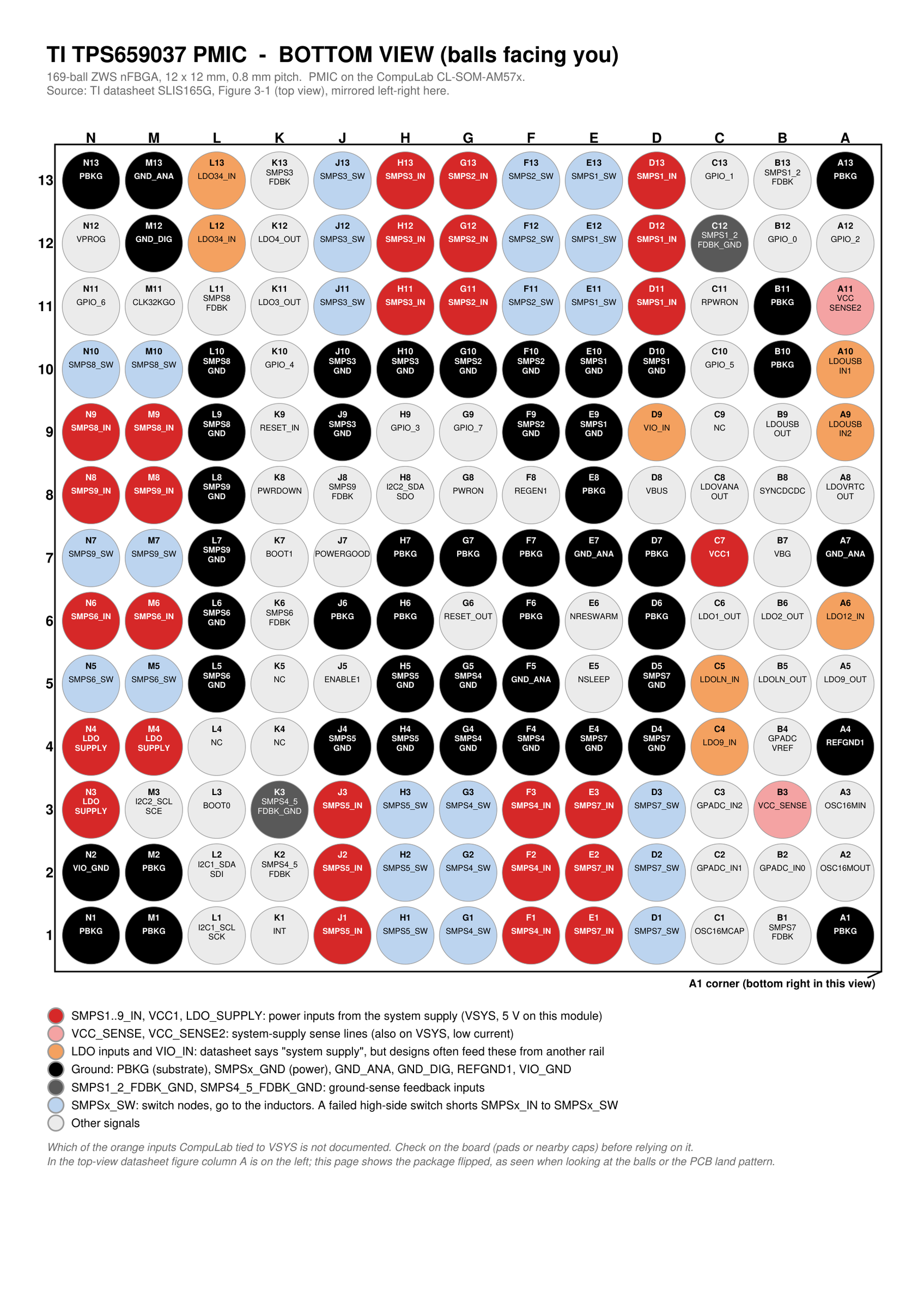
TPS659037 ball map, bottom view — tps659037_bottom_view.pdf
Finding the hot spot
A dead short does not tell you where it is with a multimeter: every VSYS pad reads the same near-zero resistance. What a short does do is get warm when current flows through it, so I put current through VSYS and looked at the module with a thermal camera.
To get the current in, I desoldered one of the VSYS input capacitors and soldered two wires to its pads. I started with the bench supply at 5 V and a 100 mA limit.
One area warmed up, and it was under the PMIC. That left the two candidates from above: the PMIC itself, or one of the small capacitors around and under it.
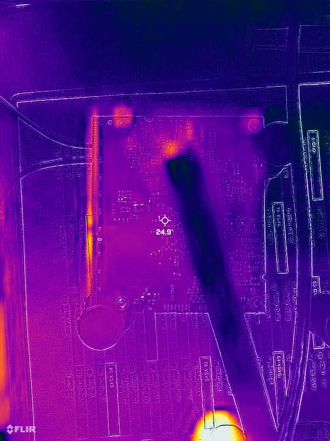
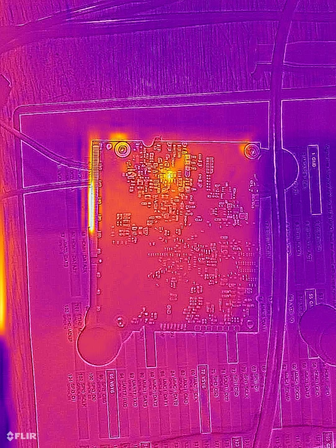
PMIC off, hot spot still there
The only way to tell which it was is to take the PMIC off. I removed it and powered VSYS again. This time I raised the current limit to 0.5 A. With the PMIC gone there was nothing downstream to damage: the only thing being stressed was the VSYS rail itself. 0.5 A was enough to show a spot on the bottom of the board. The hot spot was still there without the PMIC, so the PMIC was not the short. It had to be one of the discrete parts.
There are a lot of small capacitors on that part of the board. To know which ones were actually on the 5 V rail, I mapped the components on the 5 V path and marked their pads on a photo: blue for GND, red for VSYS 5 V, and green for any other voltage. I did not need to work out what the green ones were. It was enough to know they were not on 5 V, so they could be left alone.
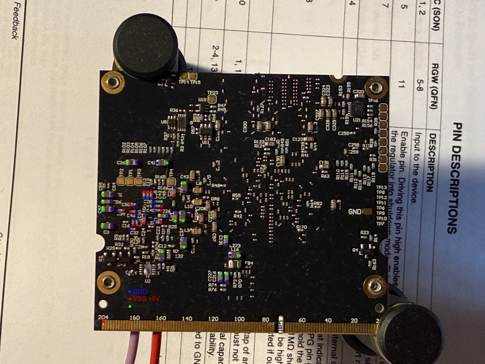
Capacitor by capacitor
With the PMIC off, I checked the board first, and this is when the capacitors came off. With the map, the method is simple, just slow: take one red-and-blue capacitor off, measure VSYS to GND, and repeat until the reading changes. Before I started it read 0.34 ohm. After a couple of tries the short was gone, and the reading went back into the kilohms.
The damaged part was one of two capacitors, C40 or C44, shorting VSYS to GND. For now both are disconnected. They and the others I took off are filtering capacitors on the 5 V input, and the module runs without them.
Checking the PMIC itself
With the board fixed, the PMIC still had to be cleared before it could go back on. A shorted regulator inside it would put the same short straight back onto VSYS.
This is what the bottom-view ball map is for. With the chip lying balls up, the sheet matches what you see, and the colours tell you what to measure: the red supply inputs against the black ground balls. The PMIC was not shorted, so it could be reused.
Back up the boot flash
Before the module went back into a printer, I read out its QSPI boot flash. It holds the bootloader and its settings, including the printer's MAC address, and it is a lot easier to save now than to rebuild later. Part 3 of the Form 3+ series explains what is in it and how to clip on.
I used a CH341A programmer and flashprog (built from source on the Mac). The chip is a W25Q32FV. Read it twice and compare, so you know the copy is good:
flashprog -p ch341a_spi -c W25Q32FV -r som_read1.bin
flashprog -p ch341a_spi -c W25Q32FV -r som_read2.bin
shasum -a 256 som_read1.bin som_read2.bin
Both reads matched, so the copy is good.
Reballing a 169-ball BGA
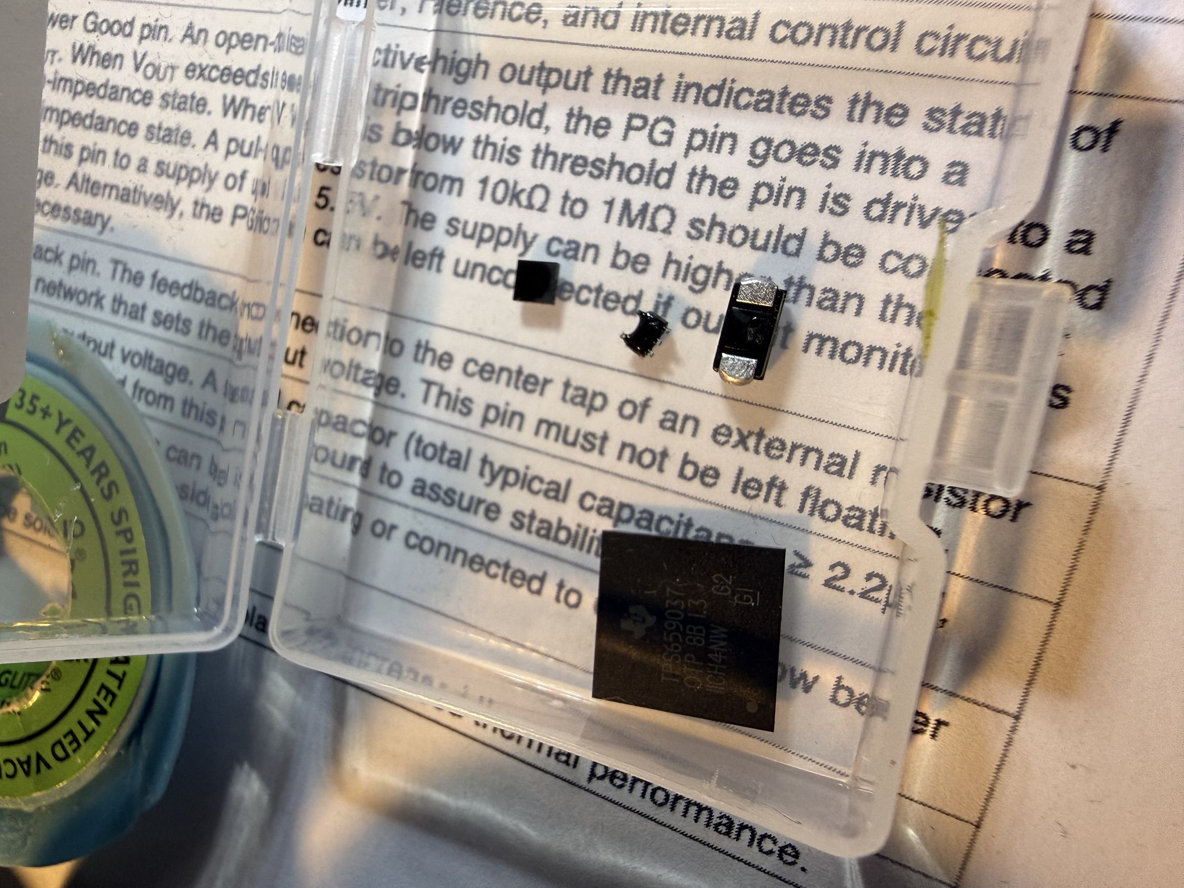
The PMIC was fine, but it had come off the board, so it needed new solder balls before it could go back on. I had not reballed a chip like this before, and it took several attempts before it was soldered down with no shorts.
What I used:
- a PMIC holder (a reballing jig) with an 80 x 80 mm stencil,
- 0.5 mm solder balls,
- solder wick and a soldering iron to clean the old solder off the chip, then a small amount of flux.
What made it hard:
- getting all the balls to sit in the stencil holes, aligned with the pads,
- setting the distance between the stencil and the chip,
- and the biggest one: getting the balls to melt onto their pads under hot air without flowing into each other and joining neighbouring balls.
Bench test
Before connecting any power to the reassembled module, I measured resistance first. I checked VSYS to GND, and GND to each of the PMIC's coils, the inductors on its switching regulator outputs. A solder bridge under the chip would show up there as a short between rails.
- VSYS to GND: back in the kilohms. With the short it had been 0.34 ohm.
- GND to the coils: kilohms on all of them except one, which read 150 ohm. That coil is on the high current rail, so a lower reading there is expected.
Only then, and before going anywhere near the printer, I fed 5 V straight into the module's VSYS pins. It drew 180 mA and stayed there. That is expected: the SOM on its own does not boot by itself, so it sits idle and the current does not climb.
Back in the printer
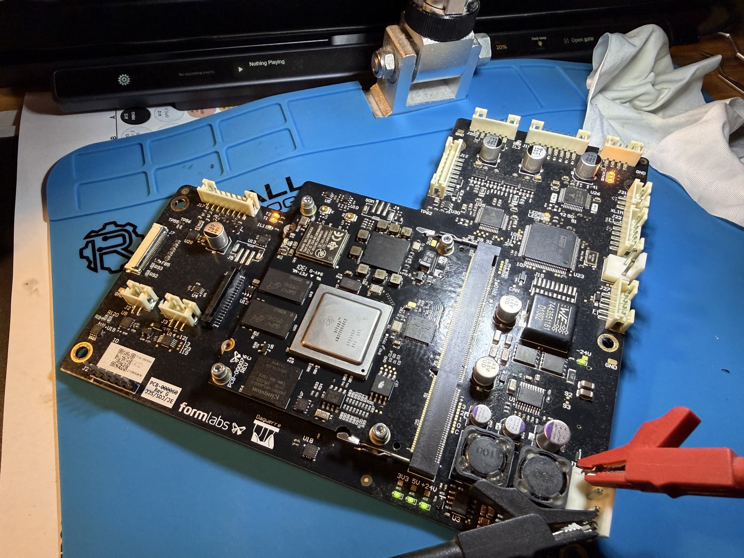
Then the module went back into the Formlabs main board, with 24 V on the main board's input:
- the 5 V and 24 V LEDs on the main board came on,
- after 5 to 10 seconds the 3.3 V rail came up,
- and both the module and the main board booted, with no shorts.
In the photo below, the three green LEDs at the bottom edge of the main board are labelled 3V3, 5V and +24V. The activity LEDs on both boards blink the same way as on my working printer, which is how I know the module and the main board are fixed. As part of checking it, I also flashed my own QSPI image, the one that connects the printer to my printer portal. Part 3 covers what that image changes.
The last check is a test print, once the printer is fully reassembled.
The whole sequence, from the first measurement to the boot:
Files and references
The two reference sheets from this post:
CL-SOM-AM57x edge connector pinout — cl-som-am57x_pinout.pdf
TPS659037 ball map, bottom view — tps659037_bottom_view.pdf
And the vendor documents they are drawn from:
- CompuLab CL-SOM-AM57x reference guide (pinout, power, electrical limits)
- CompuLab SB-SOM carrier design files, the schematics of CompuLab's own carrier. Not the Formlabs board, but the 5 V path is a useful comparison.
- TI TPS659037 datasheet
- CL-SOM-AM57x product page
Contact me
Questions, ideas, or spotted a bug? Send me a note.